There are a few ways to get the interface geometry right. One method is to measure with a ruler from a few dimensions, 3D print a test piece then iterate on any dimensions that don’t match. I have done this many times in the past, it can be quick if the dimensions are all orthogonal. The second method which I chose to do here is using a 3D scanning tool, given that the dash trim interface has a few different height planes and angles. The tool I used is Polycam, which a coworker recommended. I believe it works best on certain Iphones with LIDAR sensors, but it didn’t seem to complain on my old Xiaomi Mix3.

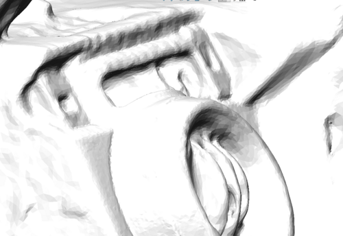
The app is pretty straight forward, from what I could gather it takes a series of images and creates a 3D model using the slight offsets between images, like getting depth from stereo vision. My first attempt was done in my dark garage, the results looked good but had some problems on close inspection.

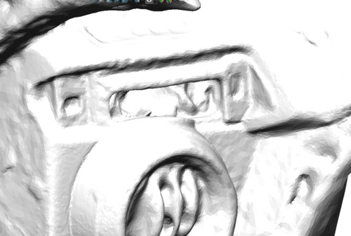
Due to the lack of contrast between the dark dash interior and the black plastic, the rectangular mounting holes appeared okay in the textured output above, but were too undefined in the stl file export in Solidworks. Also, due to using the free version of Polycam, it did not allow direct export of stl, had to find an online converter tool for GLTF to STL. To fix the issue, I realized the computer vision algorithm benefitted from having as much light as possible, and high color contrast. For the next scan, I took the car outdoors on a sunny day, and stuffed some tissue paper behind the dash trim opening so the interior is white instead of black, against the black plastic.

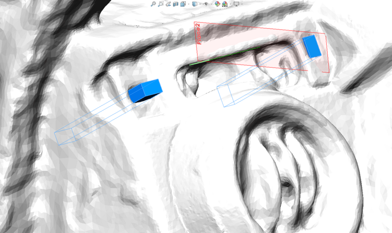
This scan turned out a lot better, and is usable for the purposes of this project. After loading it in Solidworks, it needed to be scaled (because Polycam has no idea the dimensions of the images without a LIDAR sensor).
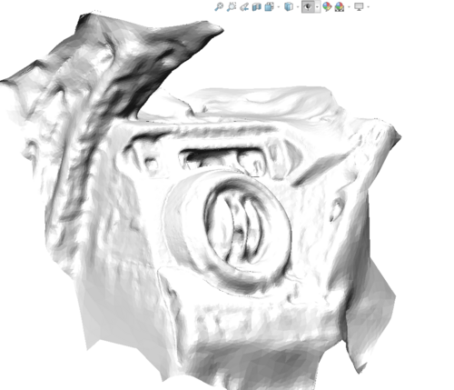
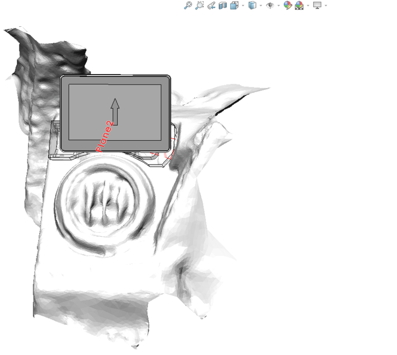
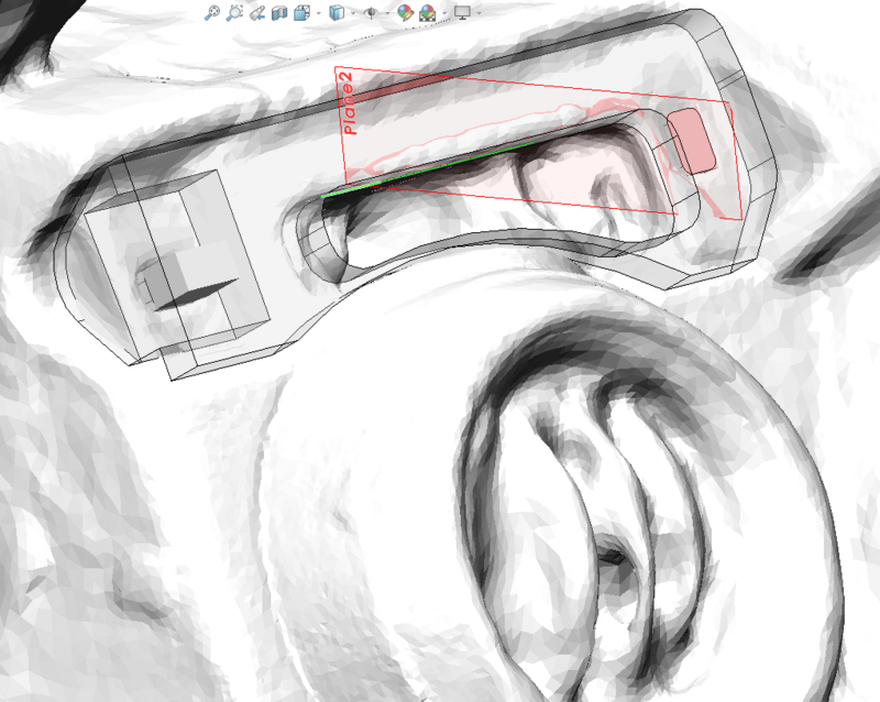
The surface looks rough due to the shading, which concerned me initially. Grabbing the now-more-pronounced square holes and two planes I intending on mating the custom mount to, I created the following reference geometries.
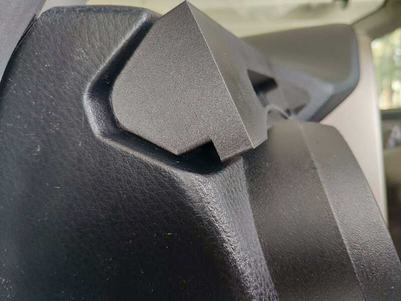
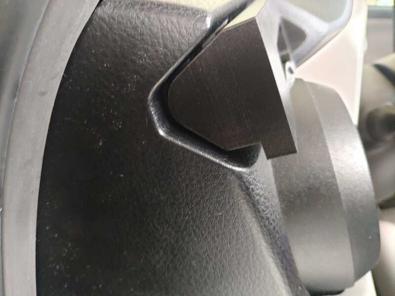
I designed this test part to fit the interface. If it succeeded I could directly take the geometries off this part and use in the actual mount.
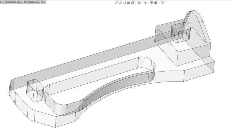
After 3D printing this test piece on a MarkForged machine, I test-fitted it. To my surprise, this method worked out very well, the piece was a transition fit into the square holes and the gaps looked very close to the CAD. This was confidence inspiring because the geometry was pretty complicated, and there was a 3D curved vent that it had to clearance.


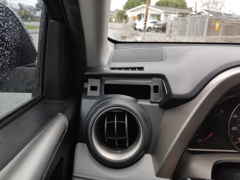
Here is a teaser of what the screen will look like to the driver. It is starting to look real!