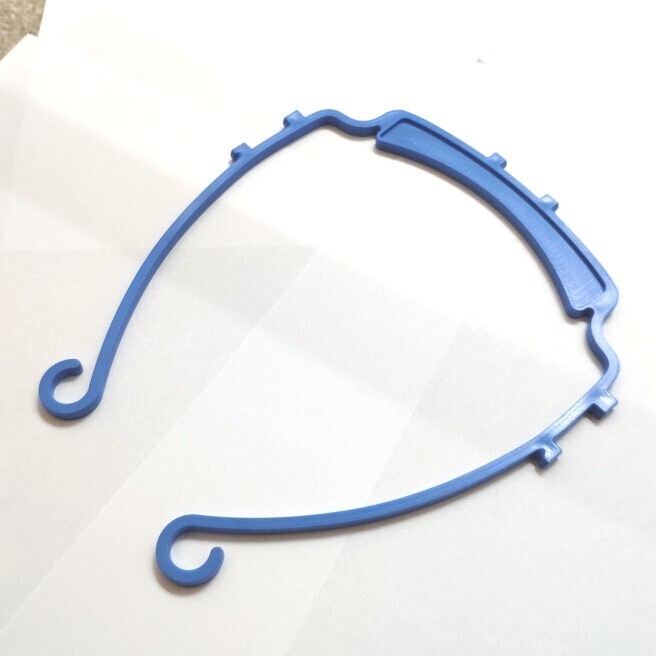
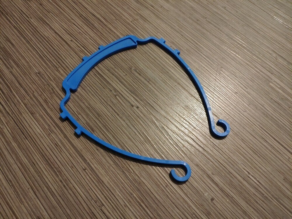
When Covid19 first hit the US, a group of makers including myself at Cornell were asked to pool our rapid prototyping resources and 3D print face shield visors for Cornell’s Weill Medical Center in NYC, which expanded to a few other surrounding hospitals. The effort was organized by a group of professors, students and community volunteers, and helped alleviate the emergency PPE shortage. This was ultimately solved through a injection molded design that we developed.
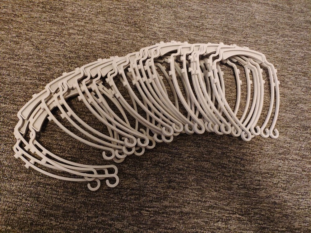
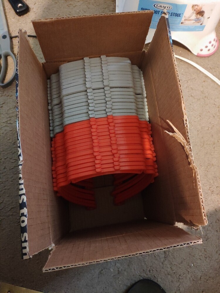
We first began 3D printing as many of the visor bands as possible. The design was an open source one by 3DVerkstan. It consisted of a single printable head band, which could be easily assembled with a letter sized laminate sheet using a 3 hole punch. In total, we printed over 10,000 visor bands and organized the delivery to NYC hospitals in need. During this initiative, I and a few others (Mark Brancale, Jiaohao Zhang, Nils Napp) proposed a better way of manufacturing these parts with injection molding, and spun up a mass-manufacturable design in a few days. The design was injection molded at Protolabs with medical grade polypropylene, at a rate of 9,000 units per day and completely satisfied the hospitals’ demand.
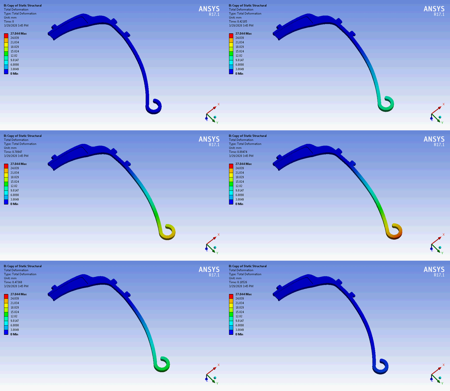
The injection molded design had to be rebuilt from the ground up due to differences in material stiffness. FEA simulation was used to ensure similar retention force to the original 3D printed design, and DFM resulted in some design tweaks to ensure thermal stability through reducing material thickness disparities. Lastly, the material choice was important, as the visors required frequent sterilization through alcohol and UV light, so medical grade PP was selected for its heat deflection temperature and chemical resistance.
Below are some news articles about this effort:
Verge: Architects and engineers are 3D printing medical gear during pandemic
Cornell Chronicle: Cross-campus effort rushes 3D-printed gear to Weill Cornell


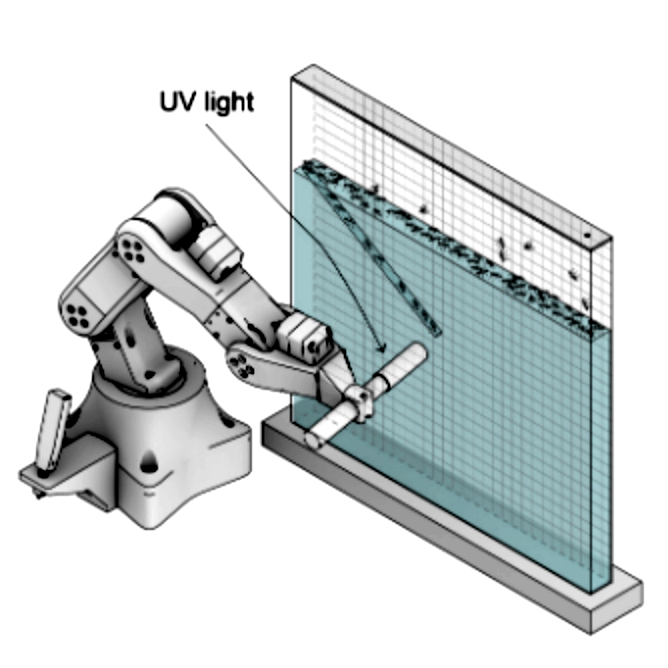
This was a research project done on the novel idea of ant-robot hybrid manufacturing, as a part of a four-person team affiliated with the Cornell Collective Embodied Intelligence Lab. I was the third author of the paper published in ACADIA 2020.
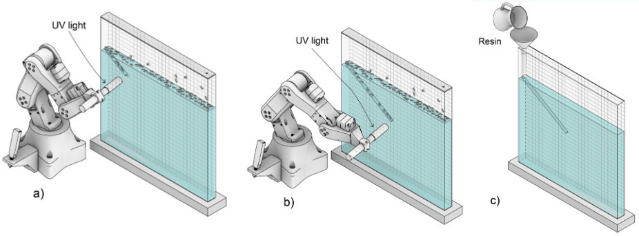
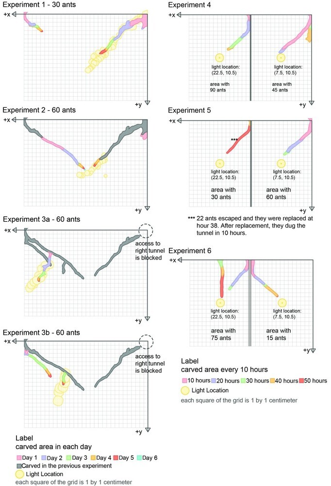
Using a robotically controlled UV light (350–405 nm) as an environmental stimulus to bias digging behavior, we guide 600 ants to dig ~141 cm of tunnels in transparent ant gel over 646 hours. Predictability, fidelity to the UV source, repeatability, dig efficiency, amount of ant activity, and tunnel preference were studied. The resulting branching tunnels were cast in silicone to demonstrate the ability to harness this in subtractive fabrication with inexpensive, self-main- taining biological fabricators.
Results showed that ants can follow the UV light as a path guide (when the light is moving) or target it as a goal (when the light is both moving and static), with longer digging effect from the moving UV stimulus. Ants showed high fidelity to the light path, aligning their tunnel direction exactly with changes in the UV position, tuning the fabrication in real-time with environmental alterations. Population size did not seem to affect digging speed or efficiency, and the ants’ preexisting preferences factored into which tunnels were dug out.
The research develops a hybrid biodigital way of working with biological swarms where the individual agency and the intrinsic stochasticity of the system offer possibilities in real-time adaptability and programmability through environmental templating.
In addition to research and working on the paper, I designed and developed most of the custom hardware and software for this project, including the robot arm and UV light system. We also presented this project at the ACADIA 2020 conference.
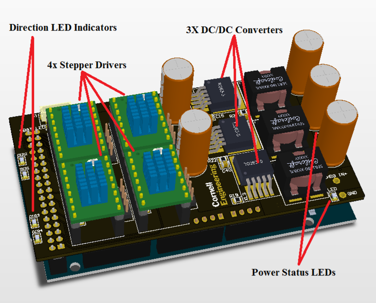
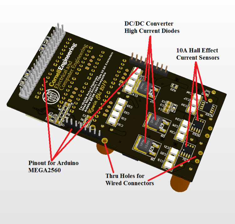
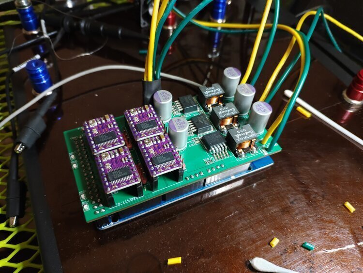
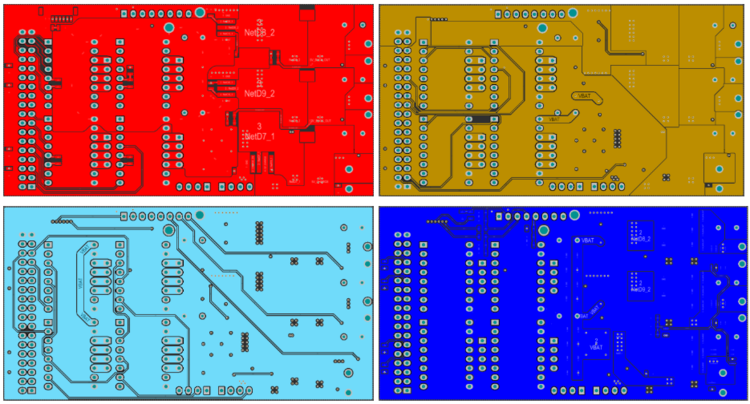
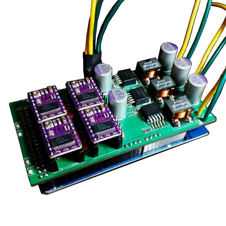
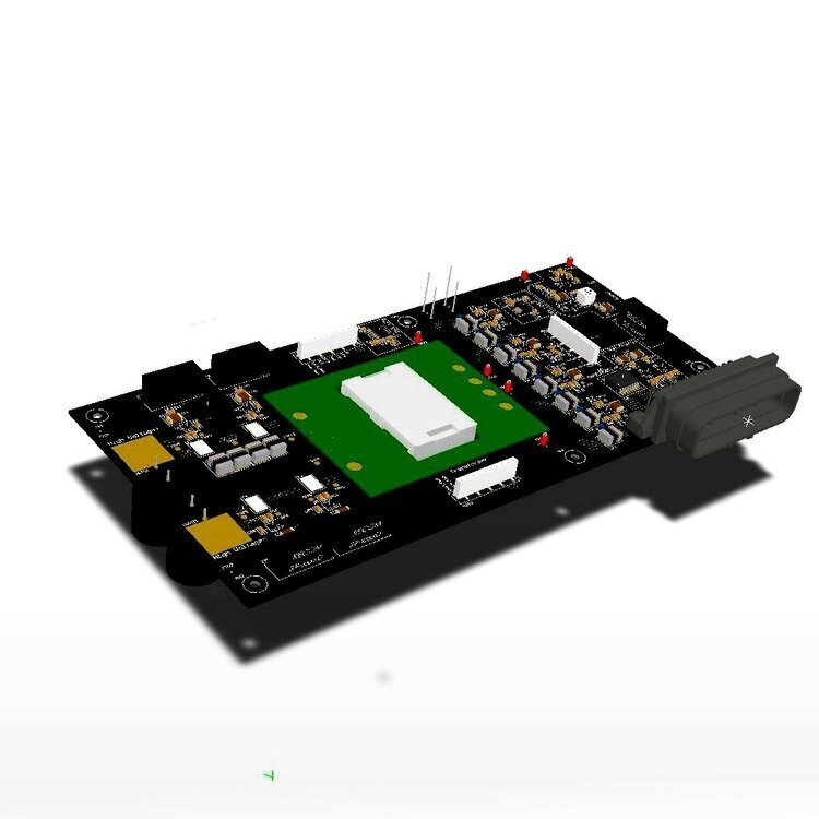
Intended for robotics applications. 4-Layer mixed signal/power design, final revision made with 2oz outer layers, 1oz inner layers with ENIG surface finish and black solder mask. Quadruple stepper drivers connected to Atmega 2560 hardware PWM, with triple DC-DC power supplies and current/voltage monitoring on all channels, and for every battery cell. Configured for 4S lithium power input, with 5V 6A buck, 12V 6A buck, and 5V 2A charging boost.
Being a combined signal and power supply board with three DC-DC converters, noise was a major concern. Not just from the switching power ICs, but also from the stepper drivers. Thus special consideration was taken to separate analog signal traces in different layers and farther distances from those components, and shielded by large power/ground planes. Moreover, optional passive filtering was included if necessary for voltage/current sensor reading. Trace lengths were optimized to reduce cross-talk.
There was also a strict size constraint to fit inside the small form factor robot chassis, thus the layout chosen was about as compact as physically possible without collision or compromising signal integrity. A shield architecture was chosen along with the Mega 2560 due to accessibility and cost goals. The board ended up costing only about 10 USD each to manufacture in China (without components), which is extremely affordable for the rich set of hardware features provided. The board took approximately 5 days to design, then a few more days after the first samples to tweak to the final version.
On the embedded software side, a custom hardware PWM acceleration algorithm was developed to allow for high-resolution, low-latency simultaneous control of 4 stepper drive motors. The algorithm takes input control commands from the serial port, with a custom command structure to maximize information density with the given baud rate. More information can be found in the long-form report and linked Github repository, available here.
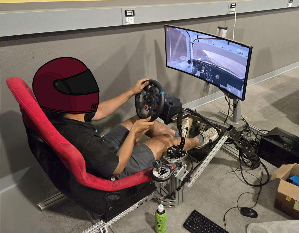
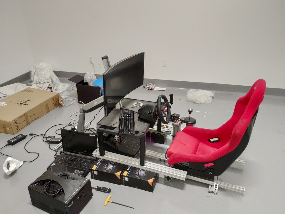
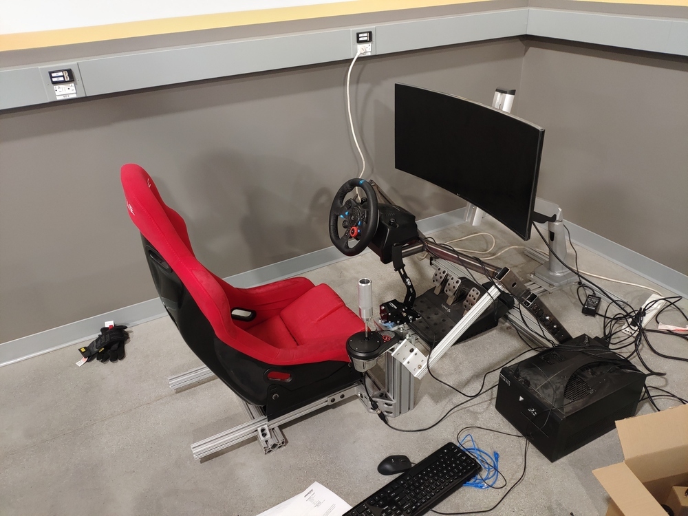
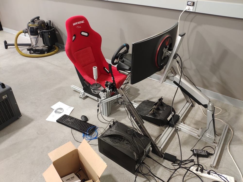
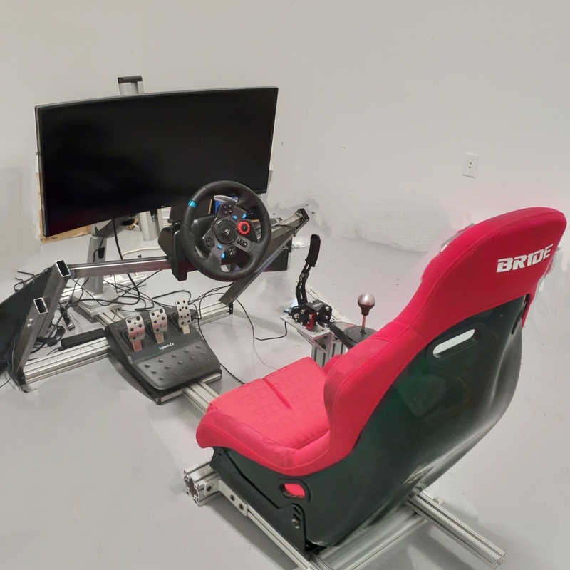
Building a custom racing simulator has been a long term dream of mine. I have been slowly collecting parts for it over the years; the (knockoff Bride LOW MAX) bucket seat I brought back from a trip to China, Logitech G29 I have had since college. I finally had access to the tools and space make it happen, and built this in 3 weekends.
Ergonomics was a difficult problem to solve. I did not want this project to turn into a design exercise in CAD, that would be too time consuming and not fun tweaking and tuning (speaking from experience in the FSAE team). Instead I built the seat mount first with the monitor on a beefy arm mounted to 8020 for maximum adjustability. I was using 8020 leftover scrap from work, so made the frame as material efficient as possible with a central member expanding horizontally at both ends. To test steering ergo with pedal box distance, I fabricated a slidable pedal mount from a scrapped aluminum sheet metal bracket, then mounted the wheel on a plastic desk. I propped up the table to get it to the appropriate z-height, and moved it along the y-axis until it was in a good driving position, shown in the first image below.
After a brief user test (the wheel feedback would move the table all over the place), I mocked up the custom steel frame using these dimensions. I chose to weld a custom frame due to the high forward leaning angle I wanted the “dash” to have similar to a real car, so that getting in and out would be easy. It would be quite difficult to build stiff 45 degree frames with 8020 without custom brackets, and the orthogonal 8020 racing sims such as this one require the user to do some gymnastics to extricate themselves. Also, I wanted to build in adjustability for different heights and y-axis distances for others to enjoy as well.
The result was a 2 part steel frame that has ~12in adjustability in the 45 degree axis, and able to slide the entire length of the center rail. With a small reinforcement rod tieing it to the shifter column, the structure sees minimal deflection under max service loads (i.e. lock-to-lock steering in rally games).
The final product has longitudinal and kick angle adjustability in the pedal box, 2 axis adjustability for the steering wheel, a rally/drift style handbrake, Thrustmaster TH8A gated manual/sequential shifter, and Logitech G29 wheel/pedals. I built the structure without any CAD, which was a good exercise for ergonomic mockups.
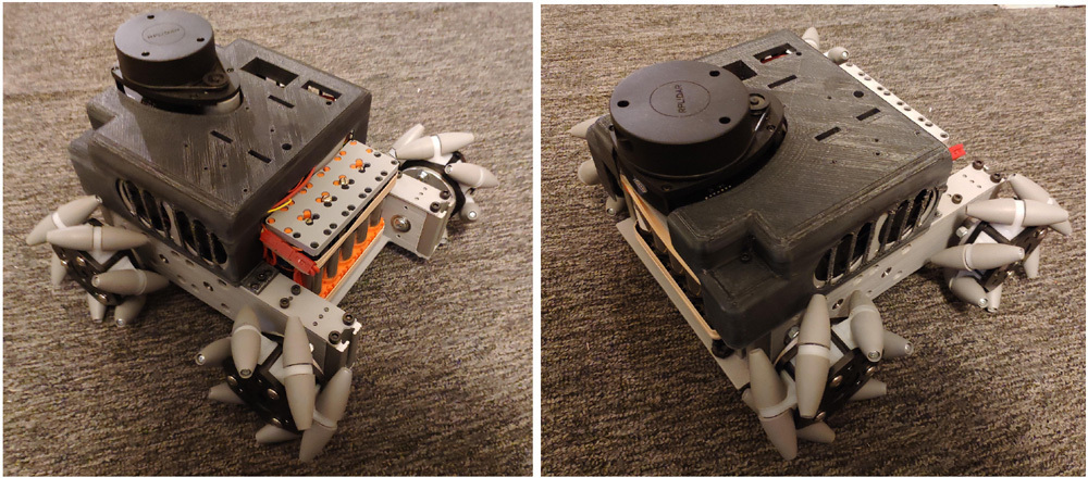
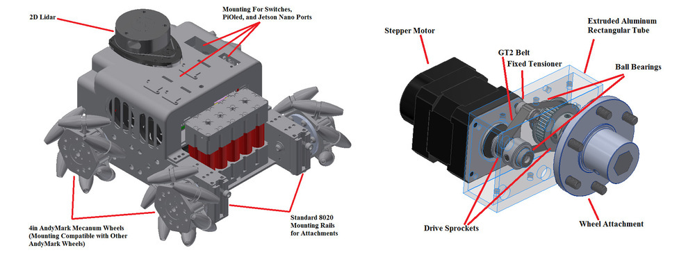
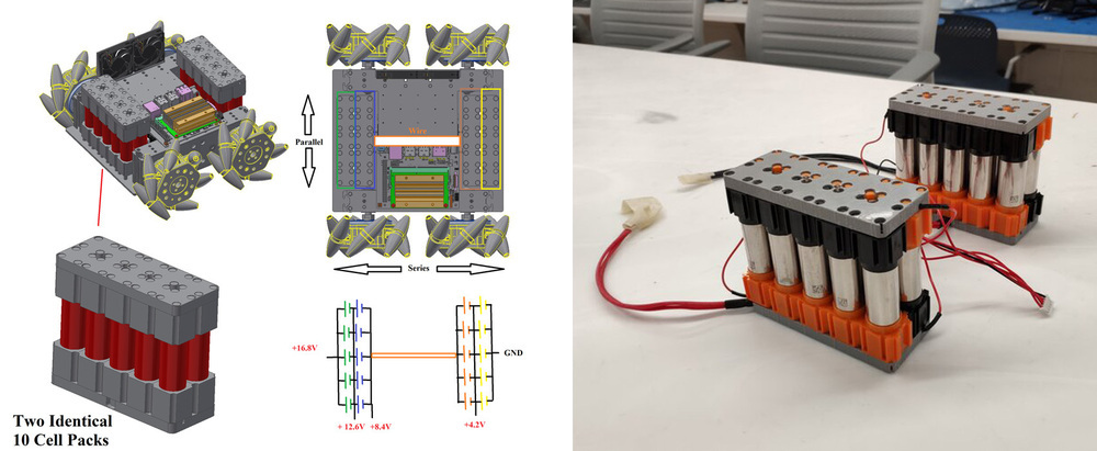
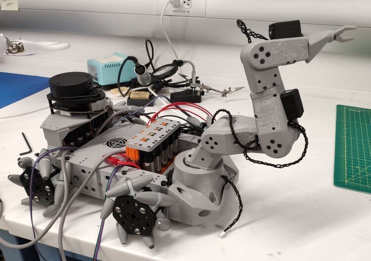
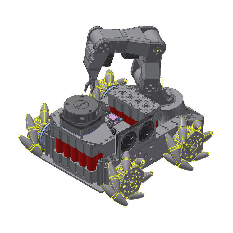
Master of Engineering project, an open source custom mobile robot platform, with Nvidia Jetson Nano, Intel Altera DE-10 Nano, and Xilinx Ultra96 Compute platforms to achieve high speed SLAM and vision based pick-and-place functionalities. Also equipped with a SLAMTEC A1M8 2D Lidar and front/rear cameras.
In addition to all the technical challenges of developing a power-dense, small-form-factor, stepper-driven robot with intelligent abilities from scratch, this project also entailed leading a team of four other engineers. This required weekly meetings, task delegations, extensive planning and integration of design progress. The effort combined mechanical, electrical and software engineering into a usable final product. While the software portion is still under development, the hardware aspect is mostly complete. Currently, I am still contributing to this project, with the goal of making it into a functional robot vacuum. The fully open source, Github project can be found here.
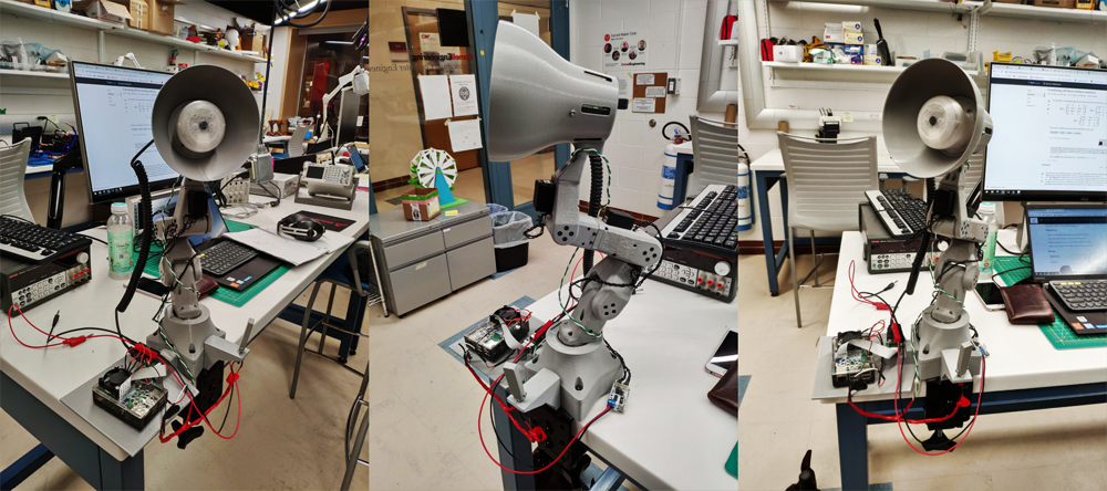
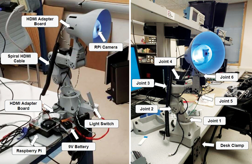
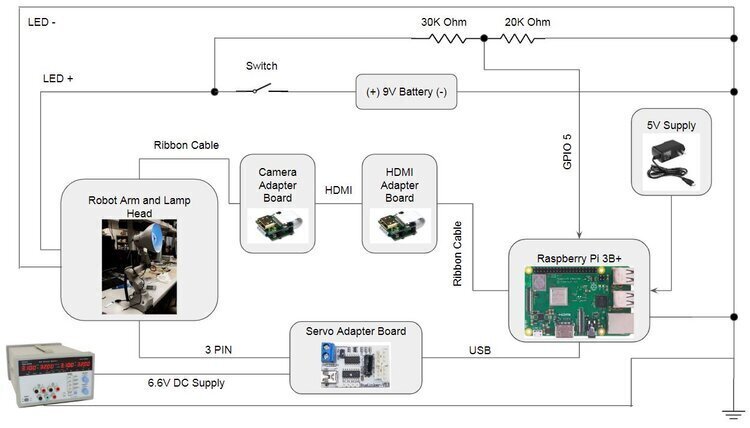
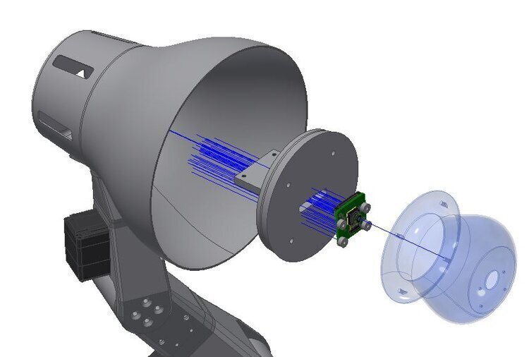
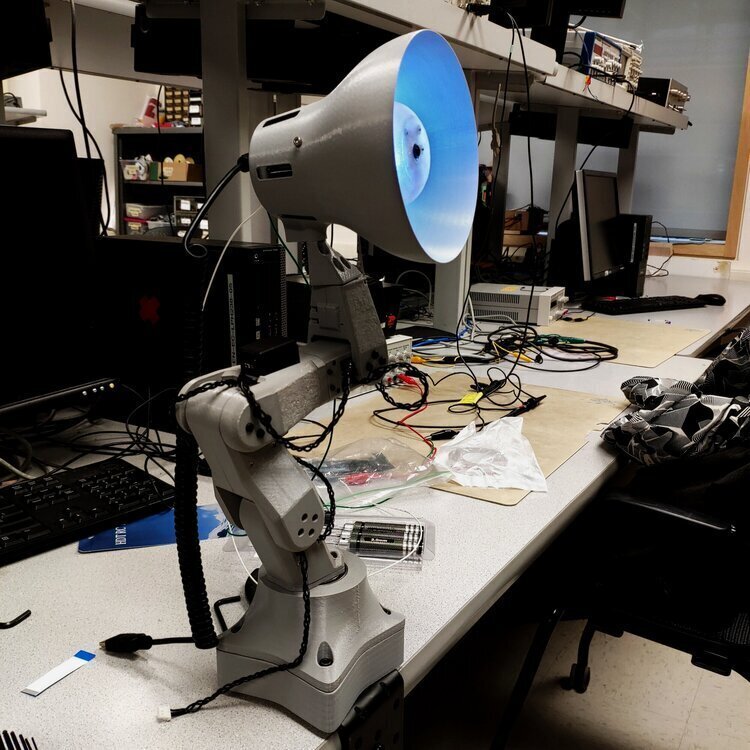
In this project, my partner and I built both the hardware and software for a social robot inspired by Pixar Animation Studio’s Luxo Jr.. For the base robot arm, we used the open-source mini 6-DOF manipulator platform that we developed (for Master of Engineering project). The end-effector, which contains both the lamp and a Raspberry Pi camera, was custom designed and manufactured for this project. To achieve organic behavior, we implemented face-detection and tracking algorithms on the Raspberry Pi 3B+. In addition, we implemented teach and replay algorithms to train the robot arm for movement routines, in order to quickly and easily achieve sophisticated motion. Overall we were successful and created a robot that is lively and interacts with humans in its surroundings, powered by a resource-restricted embedded device.
This project was done on a tight timeline of 4 weeks. There were many functionalities that had to be built from the ground up, such as motion control, face tracking, and interactive behavior. This was made more difficult by the fact that the computation was heavily restricted to a Raspberry Pi. Our development process consisted of building each modular function separately and tested in an isolated routine, then integrating the functionalities one-by-one. In the end, we built a multi-threaded python application, structured like an operating system to simultaneously handle multiple external signals. In terms of hardware, it was all custom built, and thankfully most of the robot arm was available from another ongoing project. However, it still required some design ingenuity to package the components elegantly, and for the entire module to come together as an interactive display. The website that we built to summarize the project in report form can be found here.
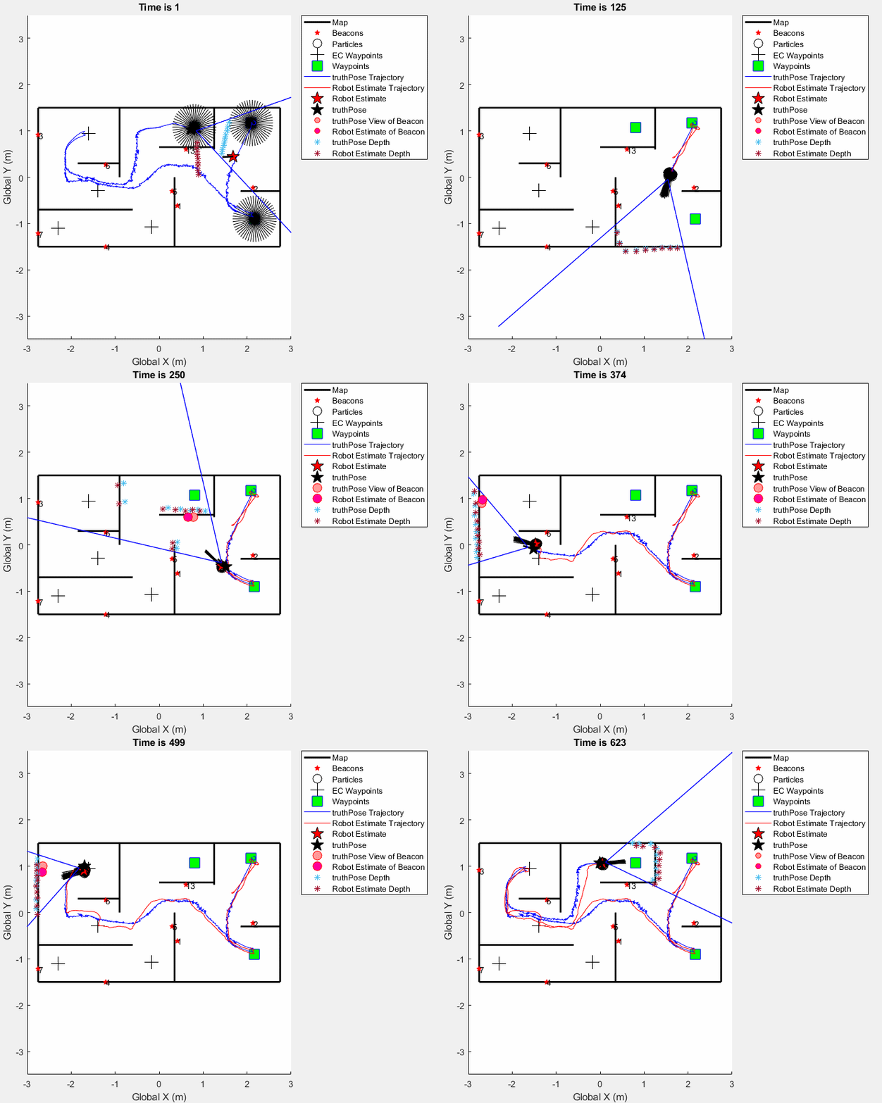
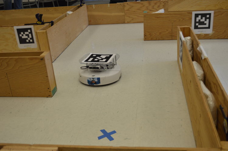

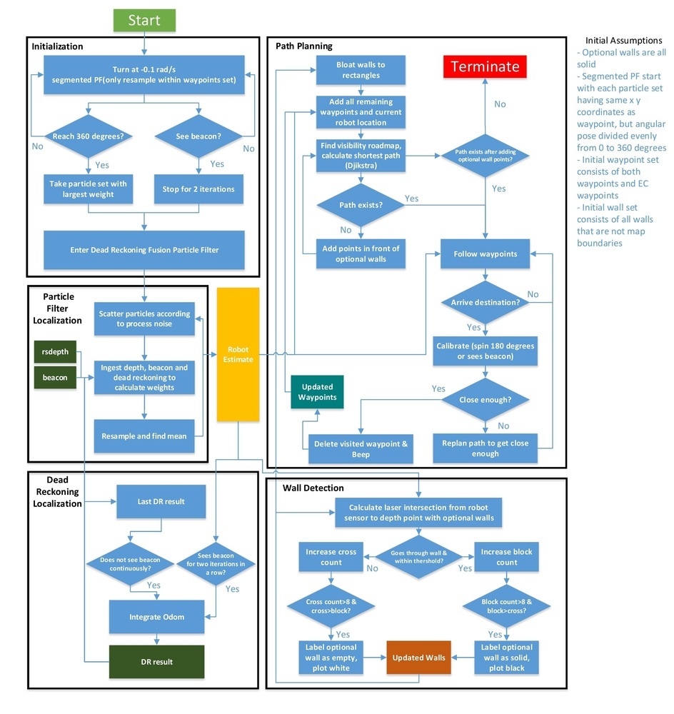
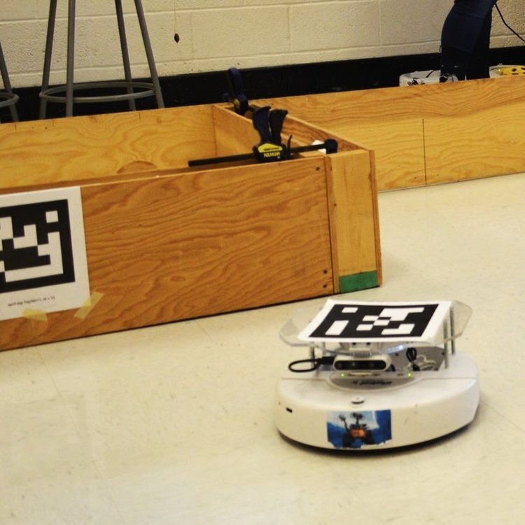
The robot is an iRobot Create with an Intel Realsense RGBD camera, and the normal iRobot suite of sensors (odometry, bump, wheel drop).
The robot is placed in one of k possible initial positions, with arbitrary orientation. The robot is tasked with:
• Localizing itself
• Determining which of the optional walls are actually in the environment and produce an actual map
• Navigating to as many of the given waypoints as possible
• No overhead localization is provided during competition, so the robot must navigate the environment “blind”.
The team’s score for the competition is calculated as follows:
• 10 points for each correct waypoint visited
• 20 points for each correct ECwaypoint visited
• -5 points every time the robot indicates incorrectly that it is at a waypoint
• 10 points for each optional wall that is correctly determined (is in the workspace or not)
• -10 points for each optional wall that is incorrectly determined (no points are deducted for optional walls that have not been determined)
• 10*(time limit (minutes) - actual time(minutes)) if all waypoints and ECwaypoints are visited before time runs out
• up to 20 points for creative and innovative solution
Our team scored 80 points (90 if you count the first beacon, we did not beep for it because we thought it was obvious), which ranked 5th in the class. I was proud of this accomplishment as we were only a two person team, and completed a complex software suite for autonomous mapping and navigation that worked well under very poor computing conditions (~1.5Hz sensor updates). Project duration was 2.5 weeks, and gave me invaluable hands-on experience with integrating a number of robotics algorithms into a single “operating system”.
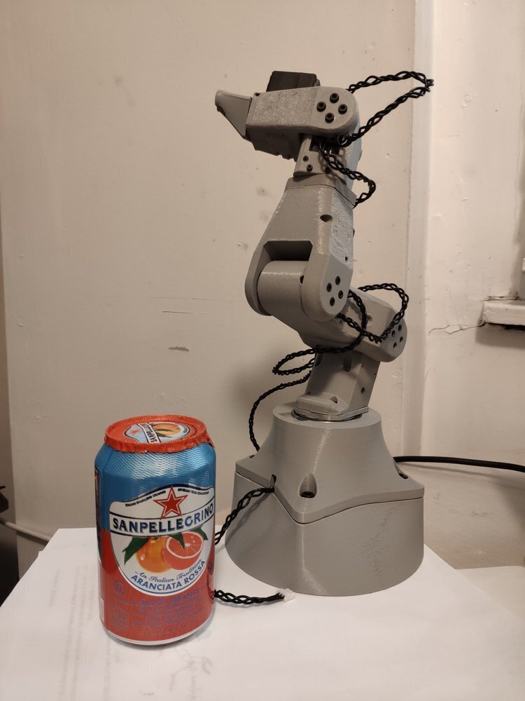
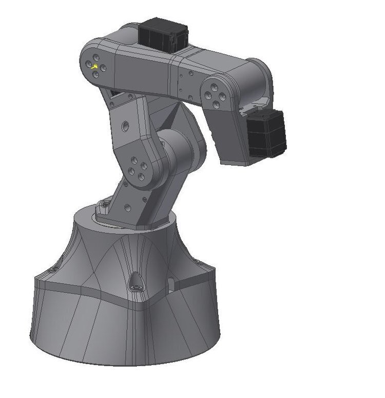
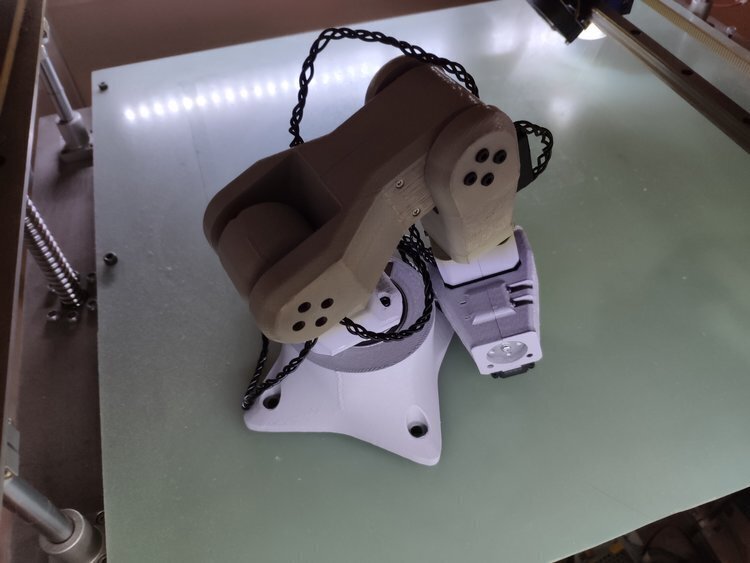
Inspired by the amazing Walter.
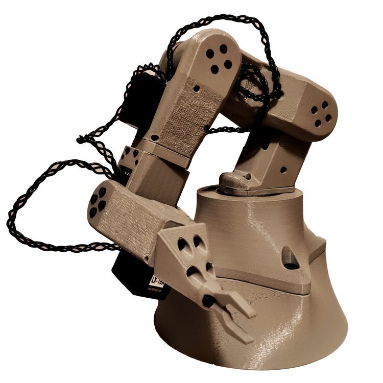
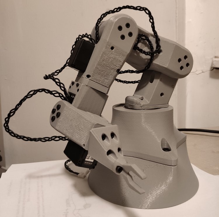
Low cost, mostly 3D printed 6 degree of freedom robot arm based on LewanSoul LX16A serial servos. Two were built, used in Open AMR, Pixar Lamp, and Ant Subtractor projects. Velocity control and ROS package work in progress.
Designing robot arms is challenging. One has to tightly package joint actuators, motion supports and electronics into a single, sleek product. Moreover, much care has to be taken to ensure that the robot arm has an adequate range of motion, and that no hardware will be damaged in different poses. For this project, it was even more challenging given that the parts have to be 3D printable with minimal supports, have to be dimensionally accurate down to 0.1mm, and be stiff enough to actuate its own mass with 6 joints. As shown in the projects mentioned above, I was ultimately successful in creating a desktop robot arm. The software package is still in progress, as that requires more hardware layer integration (I am also planning to layout a custom power/control board for it to take a wider range of voltage inputs). Currently the arm can only be programmed by manual teaching.
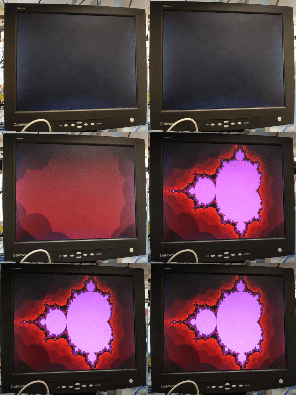
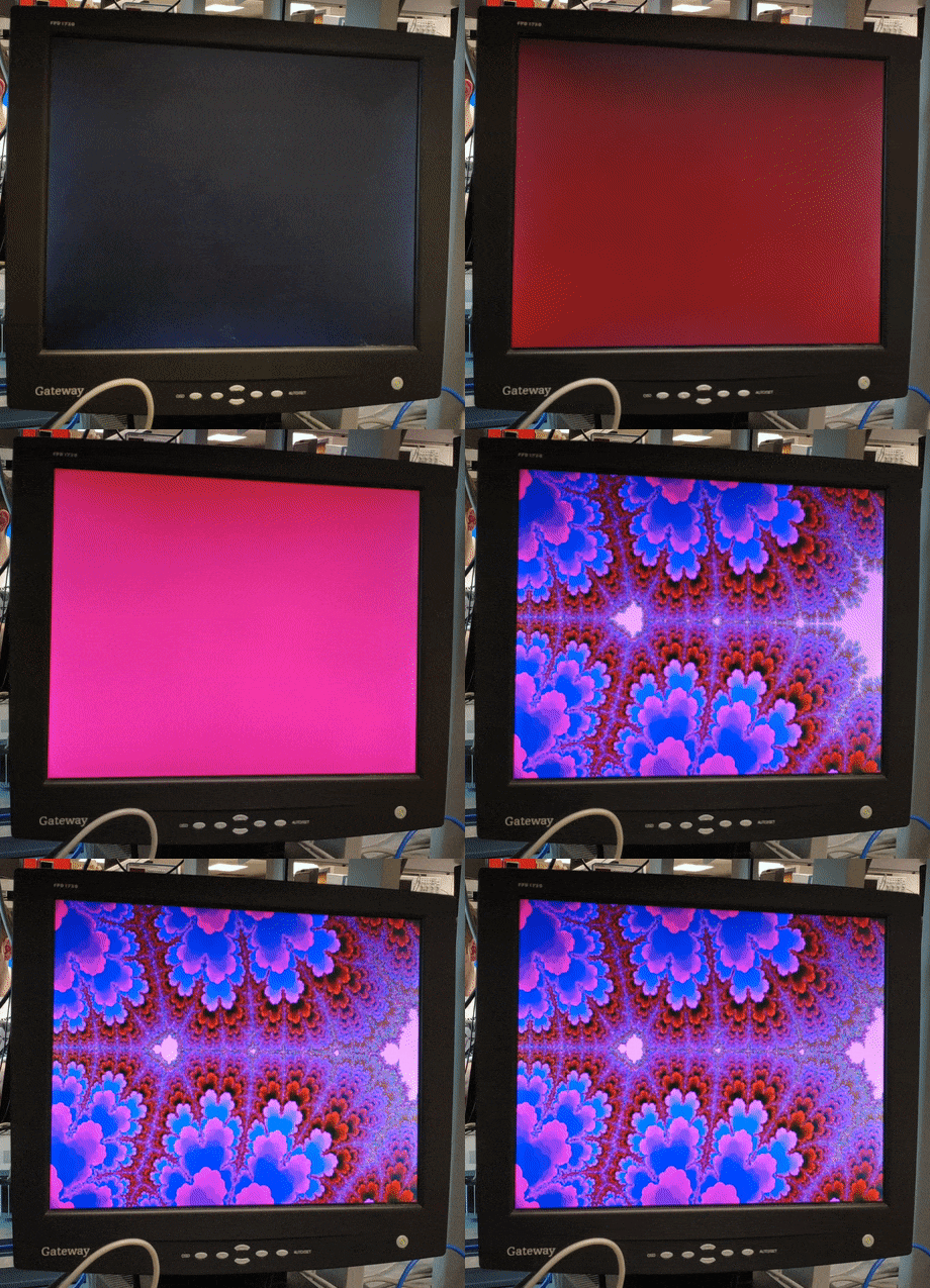

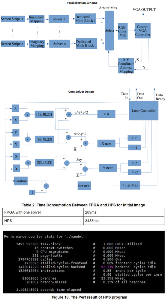
This is a completely custom implementation of the Mandelbrot Set visualization with interactive user zoom/pan using a mouse, on the Intel/Altera DE1-SoC Cyclone V FPGA board for VGA output on a 640x480 monitor. It incoporates medium-grained parallelization by dividing the screen into discrete tasks for each Mandelbrot solver, which speeds up the solution significantly. The final frequency that we could run the whole design was 75 Mhz, utilizing 100% of the FPGA resources. See data below for acceleration results. This was compared against dynamic parallelism using an ad hoc dispatching algorithm, and we found that the static task dispatching worked better because the dynamic dispatching’s calculation overhead outweighed the small amount of extra speed-up due to better parallel utilization. It is also worth mentioning that we used 4.23 fixed point for all imaginary calculations.
We compiled various .sof files that can be directly loaded into the DE1-SoC’s FPGA with varying amount of parallelism, which are located in the upper most FPGA design directory in my Github repo.
The number of iterations for the Mandelbrot algorithm can be dynamically selected in system runtime with the DE1-SoC’s 10 switches, which represent the binary encoding for that number, range 0 to 1024. The color scheme is a custom implemented version of Altera’s VGA Subsystem University Graphics IP, which resulted in a high constrast and detailed visualization that emphasizes the red tone.
This was a large FPGA project that utilized almost the entirety of the DE1-SoC’s resources. It took a few weeks of Verilog design and optimization, as well as testing to arrive at the final product. Although this is far from the cutting edge of technology, it gave me a much deeper understanding of GPU mechanisms and design, as well as parallel computation in general.
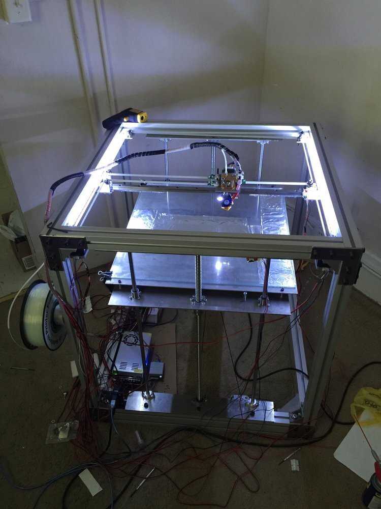
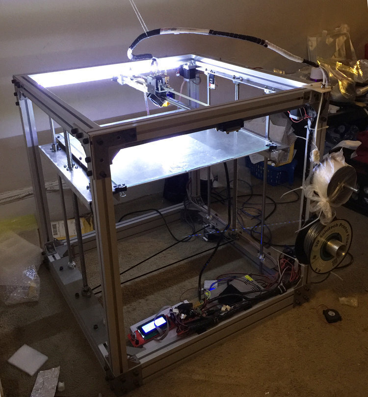
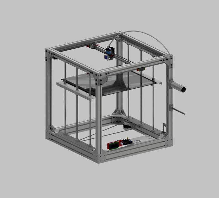
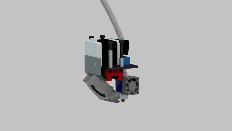
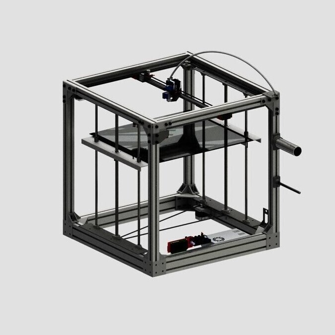
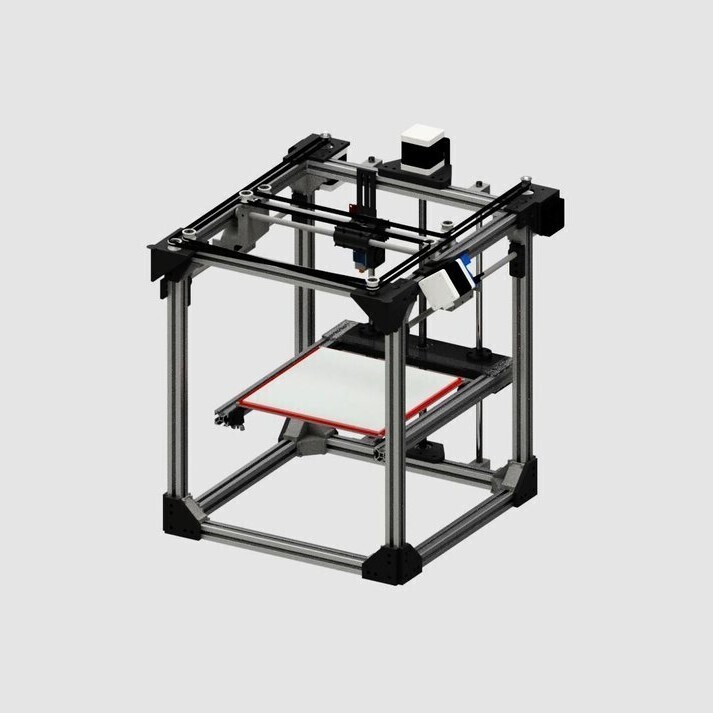
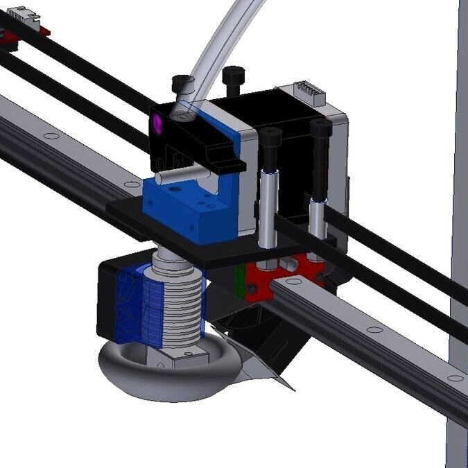
One of the crazier ideas of mine, I decided to create the printer that is designed to print printers. Project began in freshman year of college as I was extremely bored by school, and finished in that summer. With a build volume of 470x510x510mm and full metal frame and extruder, BigXY can run all filaments on the market, while achieving good production accuracy. Dual ballscrew Z axis to support the heated glass build plate, and a beefy Nema 21 stepper to drive it. Linear rail X and Y axis, powered by 2 60mm Nema 17’s running CoreXY mechanism with a direct drive E3D style extruder. The XY belt is stainless reinforced polyurethane to minimize stretch. Involved a lot of machining and a decent amount of welding to build, but only costed around $700 including electronics.
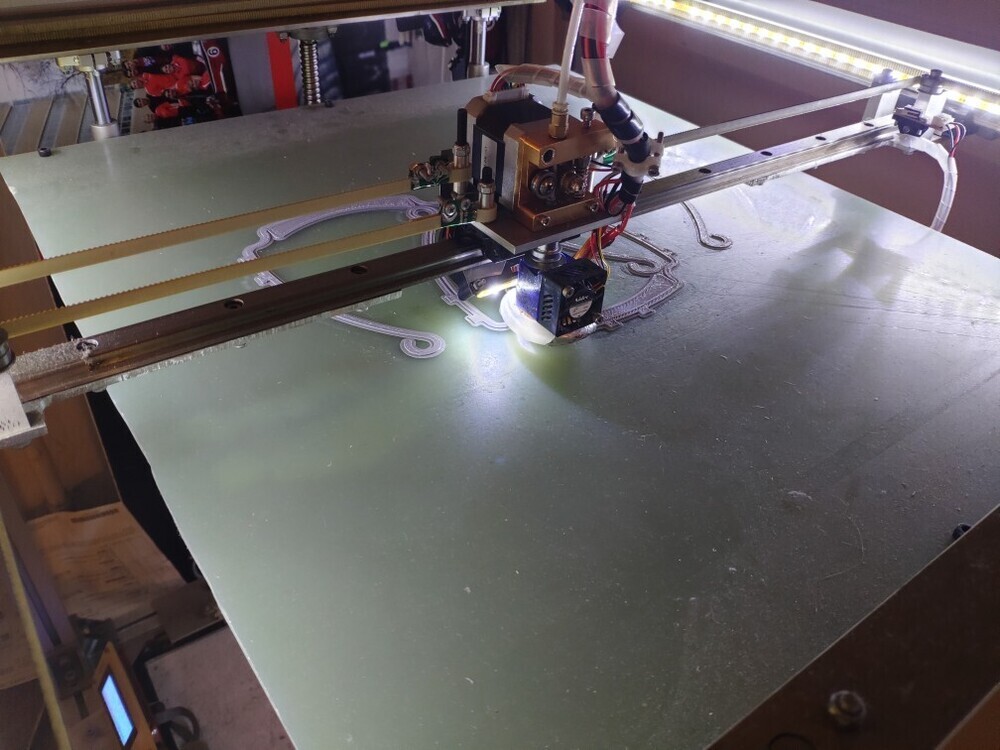
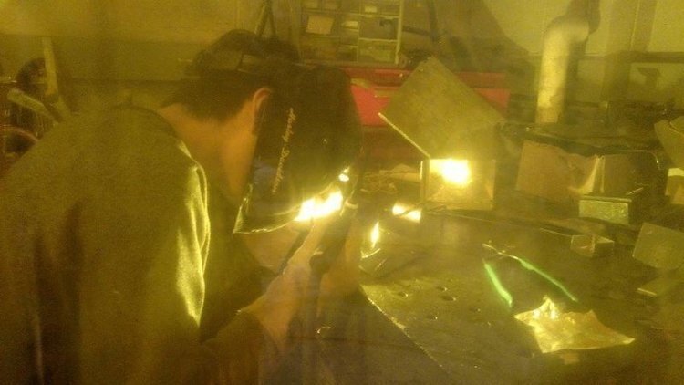
There were many challenges in this project. First, I had to design the entire printer, easily the biggest CAD assemblies I have put together from scratch at that time, and quite complex given the intricate Core XY kinematics. In addition, all of the wiring and electronics are custom made, and I had to customized the Marlin firmware to work with a Core XY architecture of this size. Then, many challenges were encountered during manufacturing. I did almost everything manually in Cornell’s machine shop over 2 weeks. The most difficult part of all were the ball screws. Being case hardened and of an irregular geometry, I had to first make a collar adapter in order to hold the ball screw inside the lathe. Then, going through the case hardened layer was very tough, and required a few days of machining time with lots of sparks and cutting fluid. I even had to weld together a motor mount for the Z axis stepper, as it needed a custom attachment geometry. The result of about a month’s work was a monstrous printer that has served me well throughout my college career of 4 years with minimal issues, and has even helped save lives during the 2020 corona virus pandemic by printing 146 face shield brackets in about a month’s time. Sadly it was disassembled when I moved for my first job, but it will be resurrected soon with updated Z stage.

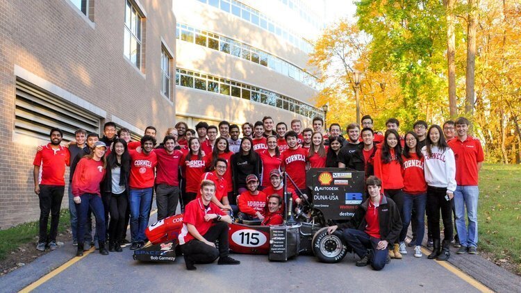
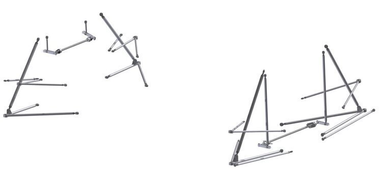
I was a part of Cornell Racing from freshman to senior year of college. Was a member of unsprung, suspension and lastly a member of the EE team. Worked on compliance testing, A-arm suspension design, monocoque manufacturing, and various other parts of the project. In my last year, we switched to an electric racecar for the first time in the team’s history, and I worked on designing the DC/DC converter.
The team consists of a group of undergraduate students dedicated to building a new and better racecar every year, to compete in the Formula SAE competitions around North America. The team has over 30 years of history, and for the past decade it has been building a fully custom carbon fiber monocoque which is quite unique to a student team.
Some specifications for ARG18, the car from 2018:
Suspension & Unsprung
• 4-wheel independent double A-arm suspension
• Pushrod-actuated Penske 7800 2-way adjustable dampers
• 7.5x10” Hoosier R25B Racing Slicks
• Adjustable front and rear anti-roll system
• Custom billet aluminum uprights, hubs, and wheel centers
Electronics
• MoTeC M400 EC
• MoTeC ADL3 Data Logger
• Modular CAN Data Acquisition
• Launch and traction control
Powertrain
• Turbocharged 4-Cylinder Honda CBR600RR engine
• BorgWarner KP-35 Turbocharger with Custom DMLS Turbine Housing
• Custom Dry Sump Lubrication System
• Chain-driven Drexler Mechanical LSD
This combined produces a 100-hp, single-seater that does 0-60mph in about 2 seconds, pulls 2.5 g’s in corners, and weighs in at just over 400lbs. Some results:
• ARG17, 8th place finish at Michigan 2017, 5th place design finalist (125 teams)
• ARG18, 12th place finish at Michigan 2018 (114 teams)
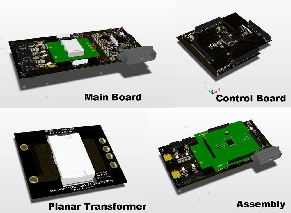
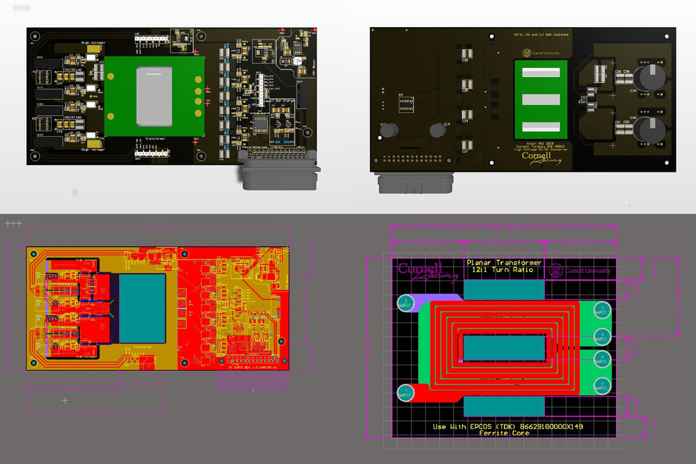

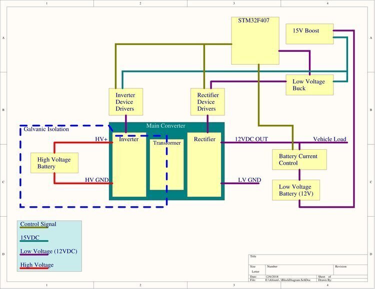
This was my senior design project, done with the help of Professor Khurram Afridi to implement a novel variation of the Dual Active Bridge topology (stacked inverter, paralleled rectifier stage) in combination with all GaN FETs to achieve reliability and ultra high efficiency. The goal was to use this for the Formula SAE electric car. Some specifications:
• 1000VDC galvanic isolation between high voltage input and low voltage output
• 280-410VDC wide input range (for this year’s racecar, but designed with 600VDC operation in mind for future years)
• 12VDC output, 400W max, projected efficiency >93% down to 10% load
• Designed to meet IP67 ingress protection rating
• Self contained module with PCB planar transformer and STM32F407 microcontroller daughter boards
• CANBUS communication with vehicle controller
This was one of the most complex PCB assembly projects I have done, and almost all of the research and work was done by just myself. Even though I was familiar with power electronics applications, I was not proficient to the level required to implement a novel architecture from scratch. Therefore I enlisted the help of Professor Afridi, who specializes in power electronics at Cornell. Even then, it required a semester worth of research and learning, much of it coming from past papers from Professor Afridi. The final design was an 6/8 layer configurable PCB, with two daughter boards for the controller and planar transformer. Two revisions of the board were done, and taken to the manufacturing stage with quoting. However, the team and I decided to stop the project there, due to budgetary and design maturity reasons.
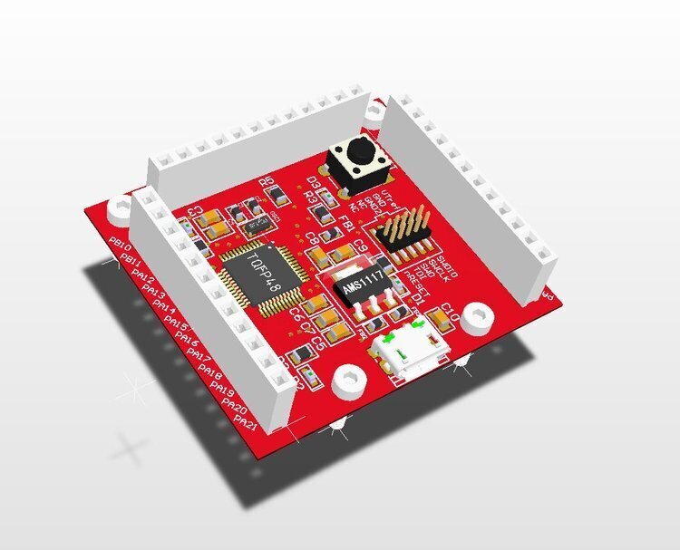
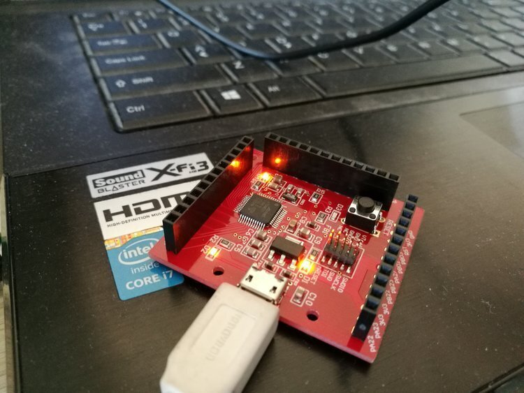
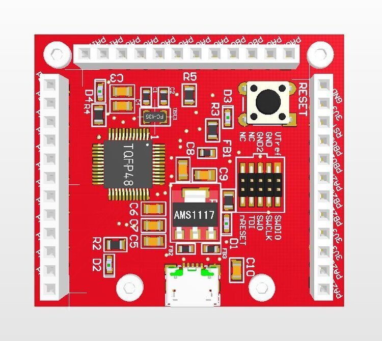
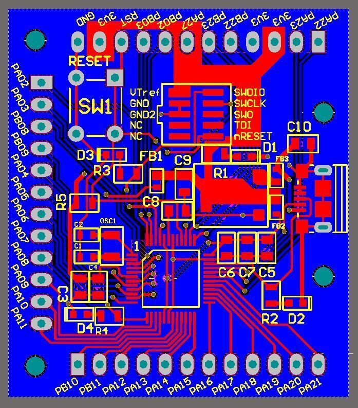
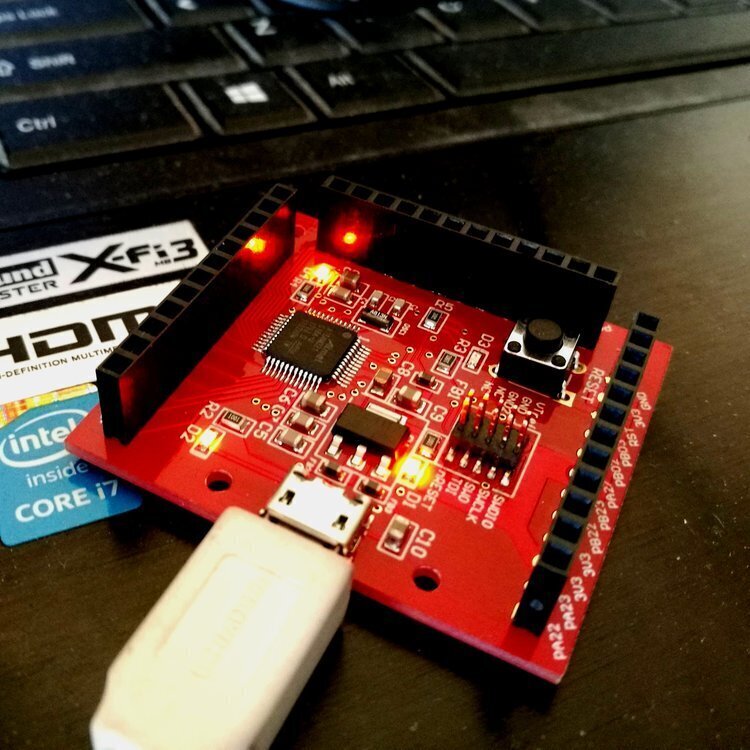
Small footprint SAMD21G18A MCU development board, measuring only 45x40mm. Based on Cortex M0, it is Arduino compatible with JTag ISP functionality. Completed in 24 hours, from start of schematics library to submission to manufacturer. Fabricated in 4 days with professional surface mount assembly.
This project was done during a holiday trip in China, as a feeler for the PCBA manufacturing pipeline there. As the results show, it was extremely efficient, as I got the boards assembled and delivered within a week of beginning the design. This gave me invaluable experience with the end-to-end process of making PCBAs, especially with tight time constraints. I am now familiar with how long each process takes, and why.

ECE 4760 Final Project Website
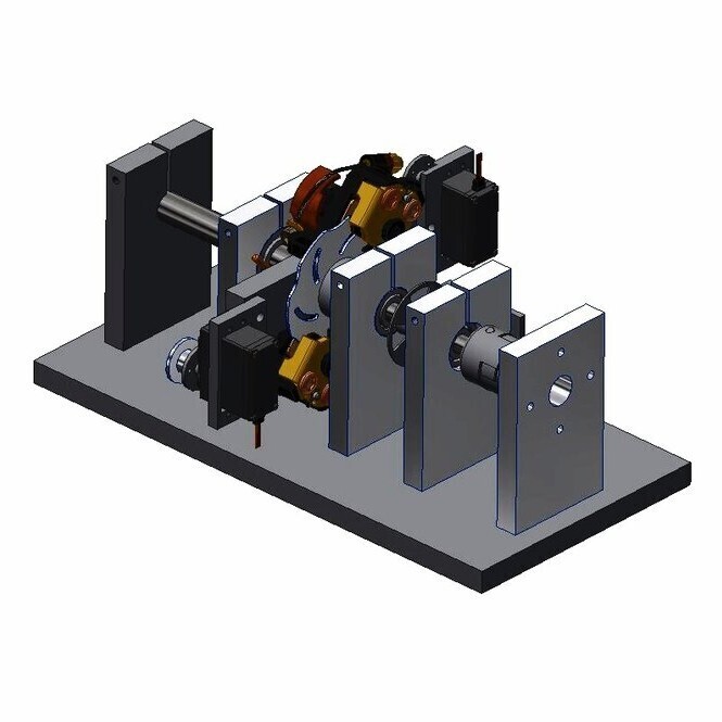
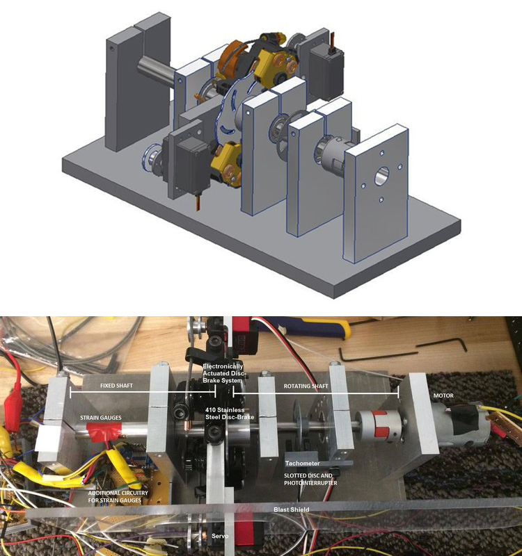
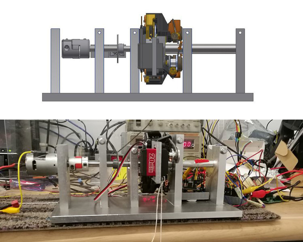
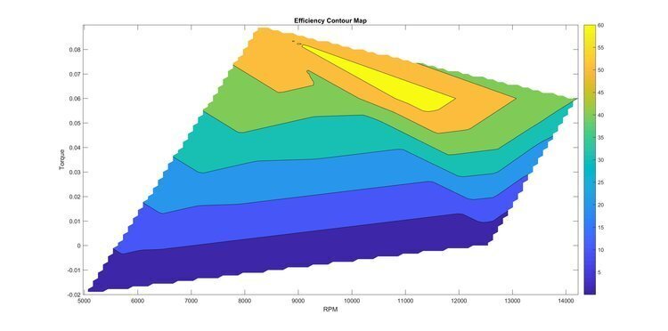
Small scale electric motor dynamometer developed for the Resistance Racing Shell Eco Marathon team and presented as the ECE 4760 Microcontrollers course final project. Based on the PIC32 MCU platform, with mostly custom designed and machined components. Goal of the project is to test the viability of producing an efficiency map similar to this one (from ANSYS, Inc.), giving a parametric evaluation of the motor performance and efficiency across a broad range of operating conditions. Basic theory is to measure RPM at various torque loads applied through a novel servo actuated brake mechanism, and derive mechanical power from that. The torque is measured through the elastic deformation of a thin 3003 aluminum tube, by reading a pair of strain gages mounted on its surface. The electrical power is measured via the ADC and a hall-effect current sensor.
The whole project was brainstormed, designed and built in a span of 4 weeks, and was featured on popular makers’ blog Hackaday. I worked with two others for the electrical and programming aspects, and a number of team members assisted in mechanical fabrication. A big challenge was the mechanical and electrical integration, as well as the implementation of the complex functionalities we designed. Overall we were able to achieve a great proof of concept.
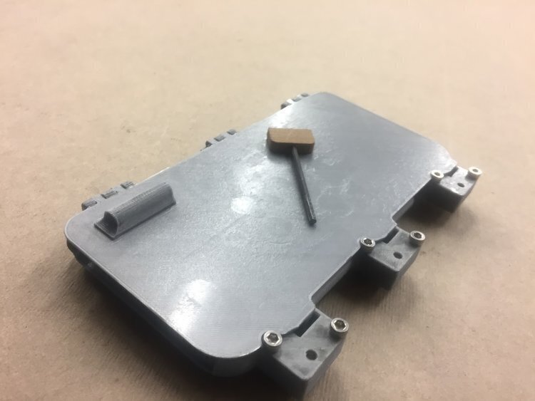
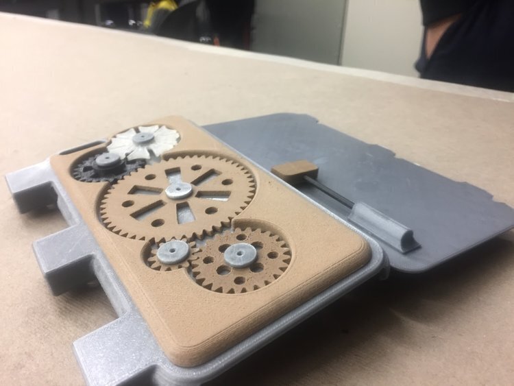
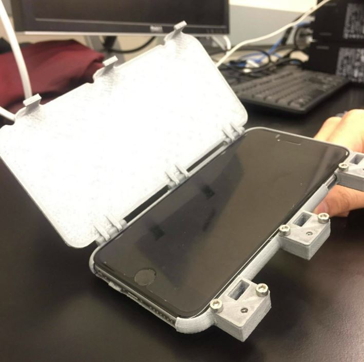
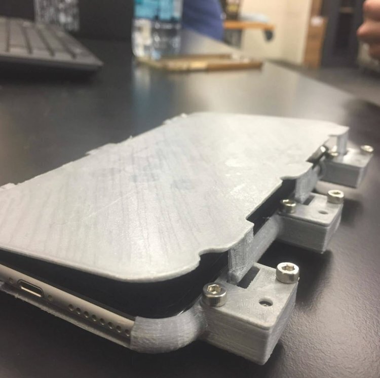
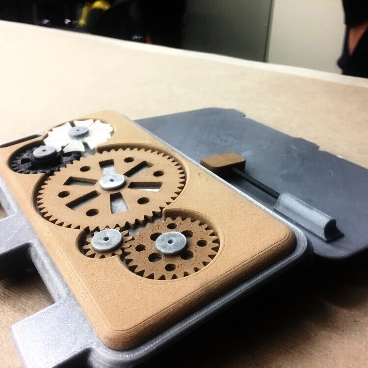
A phone case that fits the Iphone 6 Plus, with unique mechanisms on the back, turn key CW to lock, CCW to unlock.
Developed for Open Design Project, as a part of MAE 2250 course at Cornell University where it won the Outstanding Design Project award.
The challenge was to design a study aid based on user-needs interview with students, and this is our findings:
The user has extensive, sometimes even excessive interaction with electronic devices, particularly the phone, and is often distracted by it. We decided to create a device that would reduce that distracting interaction. This will promote successful and worthwhile studying to ensure the student’s success in his/her final exams. The design we came up with is a phone case which can be locked with multiple mechanisms, and has a fidgeting “toy” to help direct the user away from the device inside.
Use 1.75mm filament as hinge pins, and glue the flange/gear pins onto the case. 9X 8mm M3 socket cap screws and 1X 2.5mm hex key are needed for assembly. 2.5mm hex key also acts as the key to the lock.
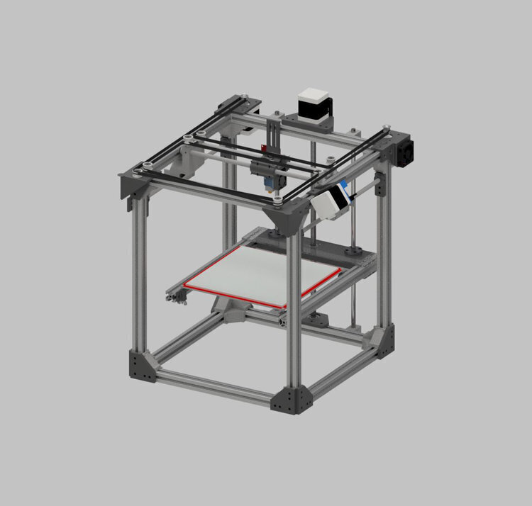
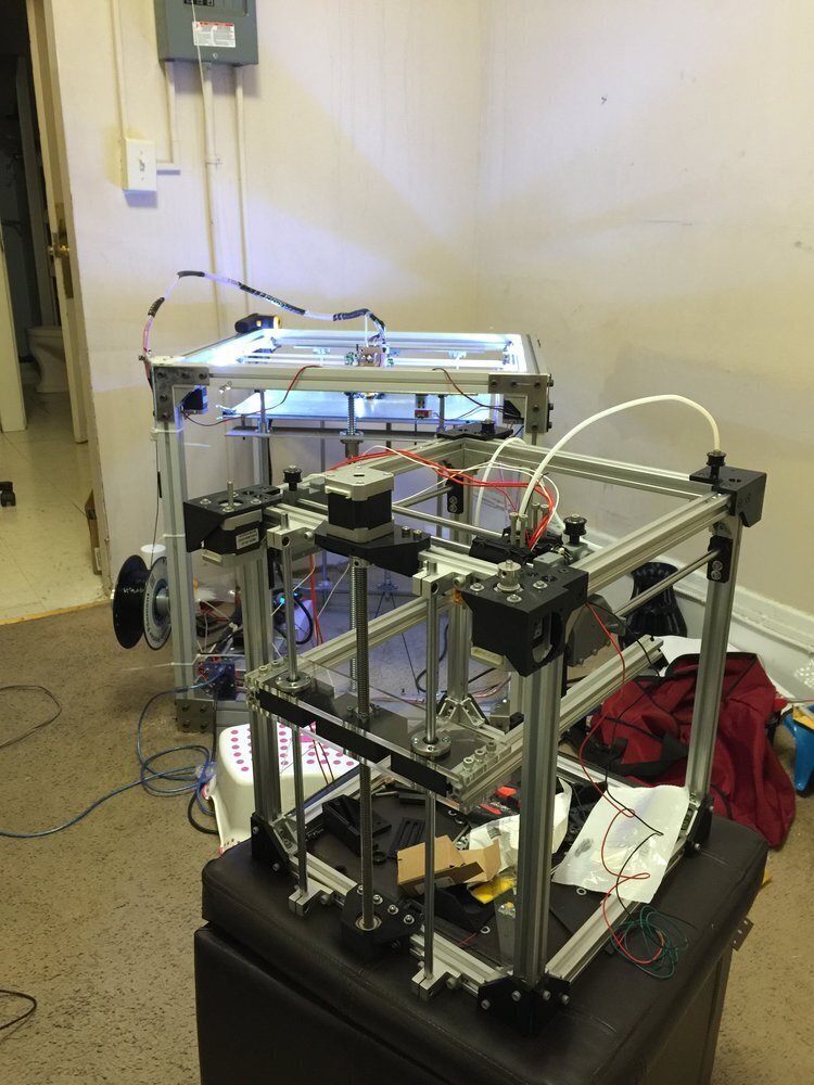
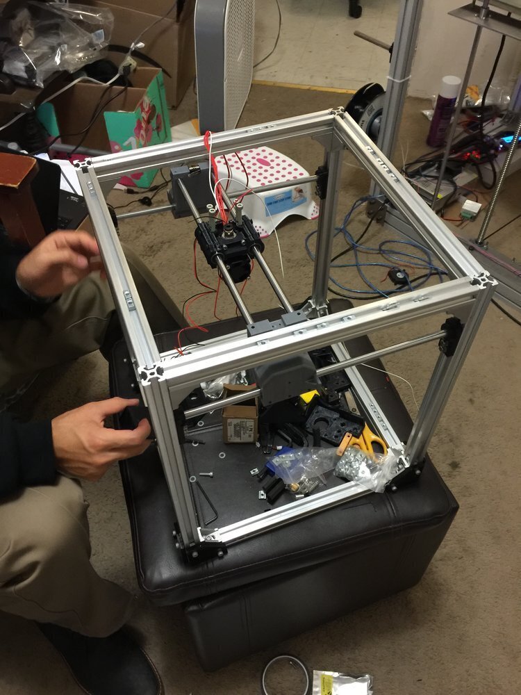
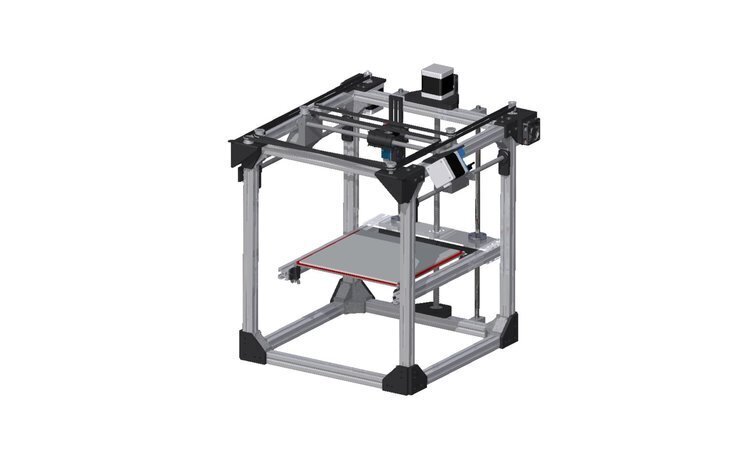
A Reprap inspired CoreXY printer, designed from scratch for best footprint/volume utilization, cost and print speed. Print volume ~ 209x220x273mm. Uses many printed parts, and cheap off the shelf components. Costs around $300 to build including electronics, perfect for people looking to get into 3D printing. First prototype built and running since 2016.
This was built after Big XY, so I used many of the lessons learned from that on this printer. The main challenge was to make the printer as affordable as possible, and make most of the components 3D printed. The other design consideration was space efficiency, so as shown the final product was very compact for its capabilities.
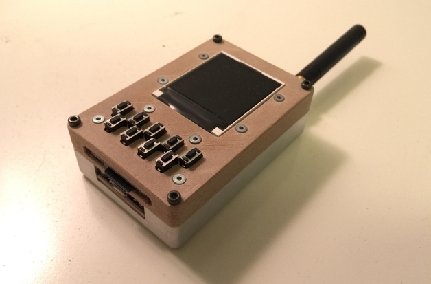
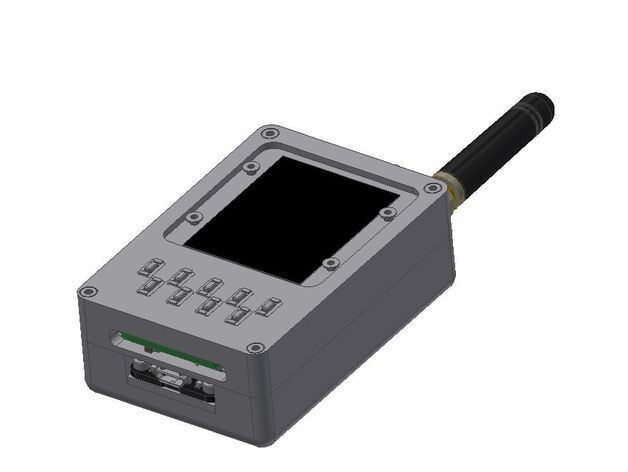
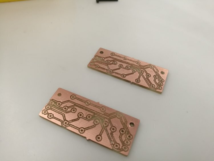
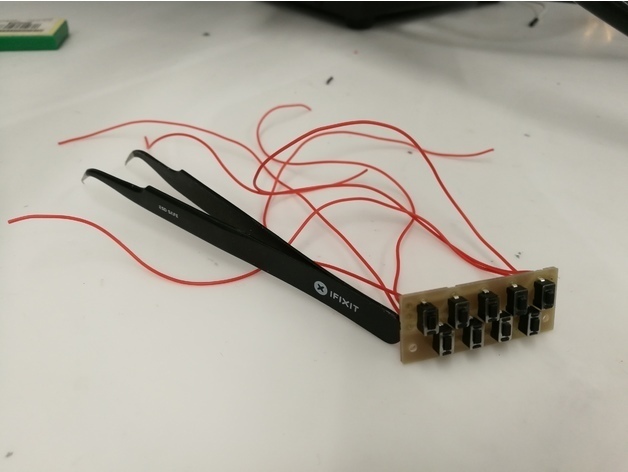
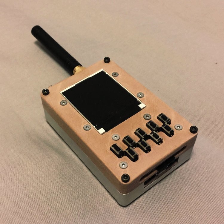
Handheld Multipurpose RF Data Logger with reconfigurable UI and SD card expansion, powered by an Adafruit Feather M0 with RFM69 radio packet. Currently configured for 1Ghz ISM band, with custom designed miniature 9-key keypad and 128x128 pixel TFT LCD. Rear enclosure is CNC machined from billet aluminum 6061, front cover is 3D printed with faux wood filament to achieve a minimalist and elegant design. With built in 2000mah Lipo pouch cell, this device can last for a year without needing to recharge.
On the software side, I was able to get the Feather M0 to run triple independent high speed SPI communication at 12Mhz, to update the TFT and transmit data to the RF module and SD card.
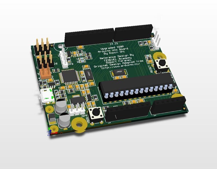
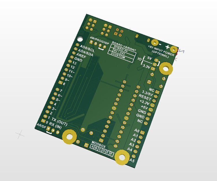
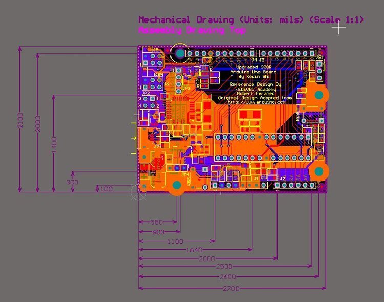
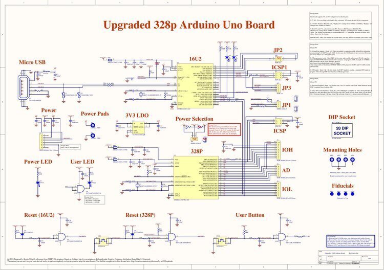
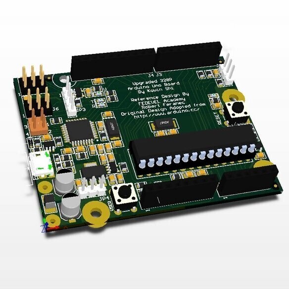
Design done as a part of the Udemy course “Learn to Design Your Own Boards“. Improvements over the standard Arduino 328p design include replaceable MCU DIP socket interface, proper ground/power planes, optimized power filtering as recommended by Atmel, and both 3V3/5V IO variants.
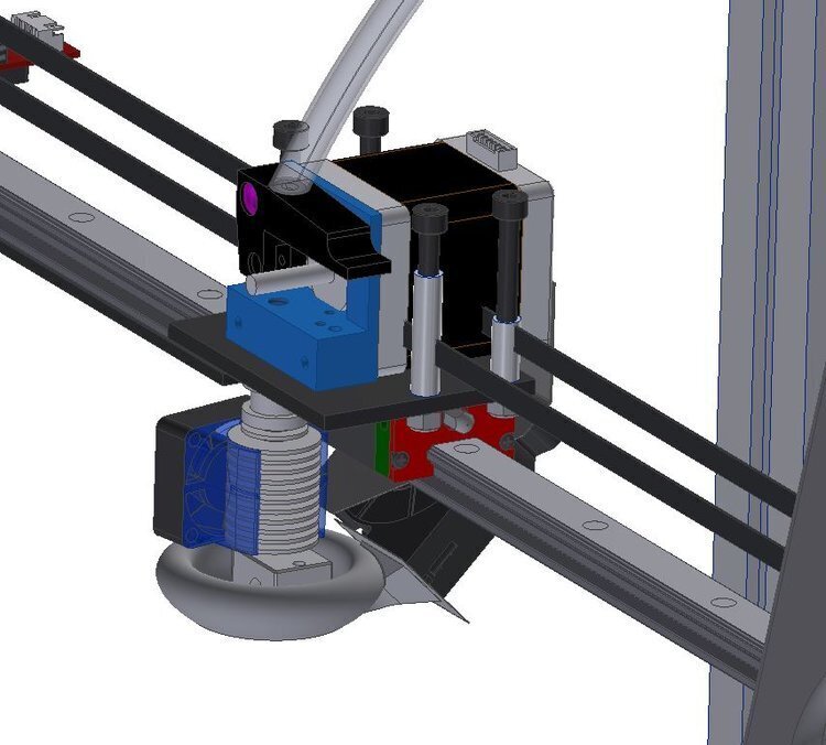
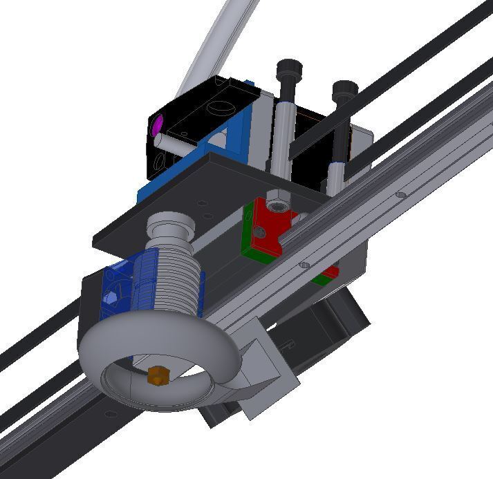
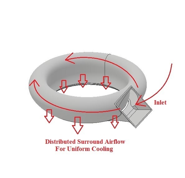
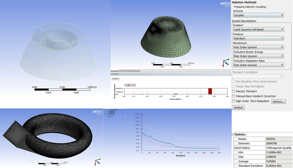
This was a part of the continued improvement process for my BigXY 3D printer. As with all FDM printers, thermal management can make a huge difference to the finish and tolerance of the finished part. Originally I just had an axial fan blowing from one side of the extruder, but with thin and tall parts, this skewed the part towards the cooled side due to the thermal stress differential. So I designed a 360 surround cooling fan duct, which worked fabulously although I did not know how to do CFD analysis at the time. Now that I had a dedicated simulation workstation, I decided to verify numerically the observed empirical results. The inlet velocity was chosen to be 8m/s from the fan’s flow rate specification, and a laminar inlet profile was assumed (which is obviously an ideal assumption). The realizable k-e model was used in Fluent CFD, and the post-processed results indeed show a well distributed airflow from particle tracking, with a velocity concentration right in the region of where the nozzle would have just finished laying down melted filament. This was very similar to my original design intent as shown below.
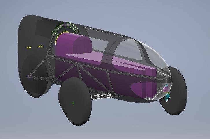
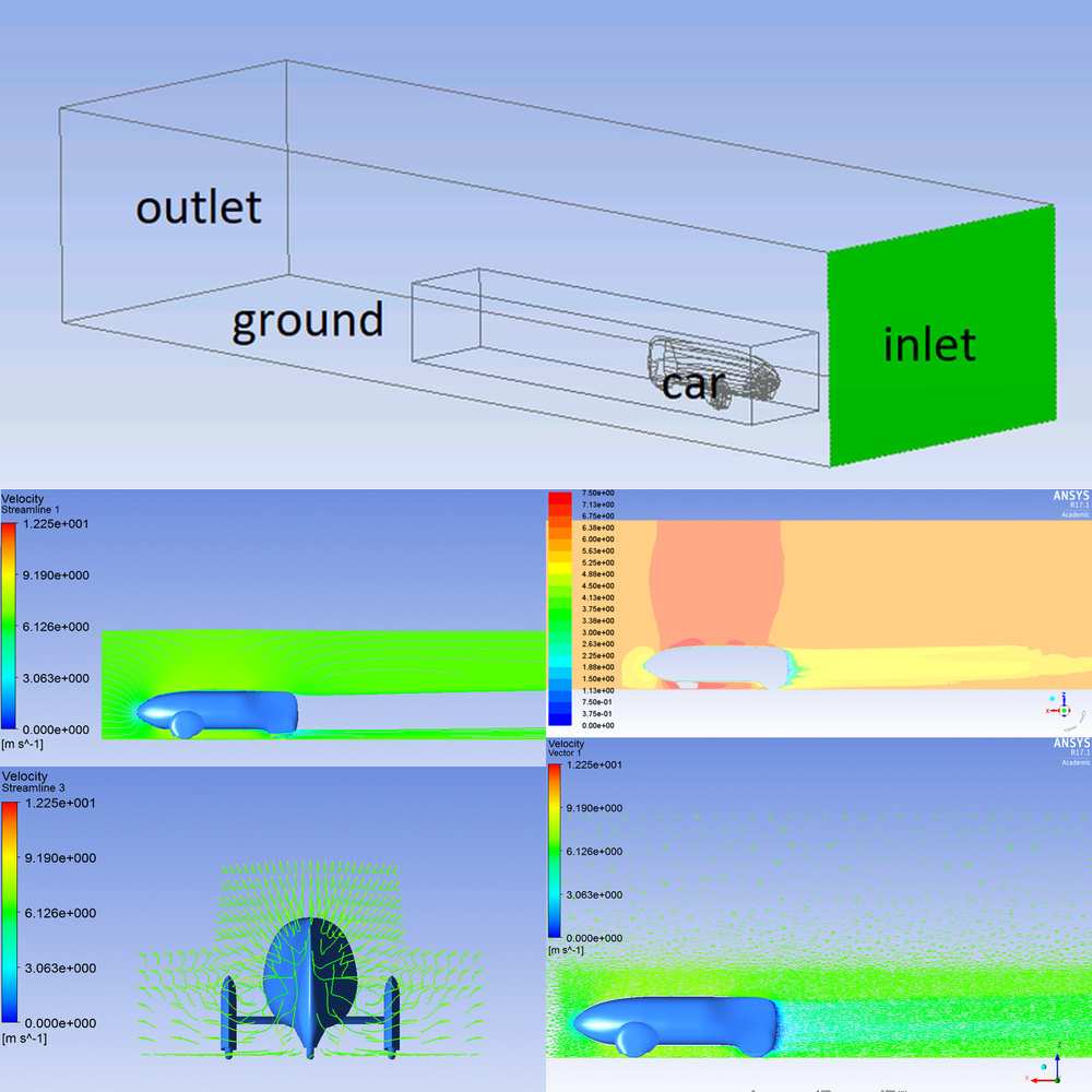
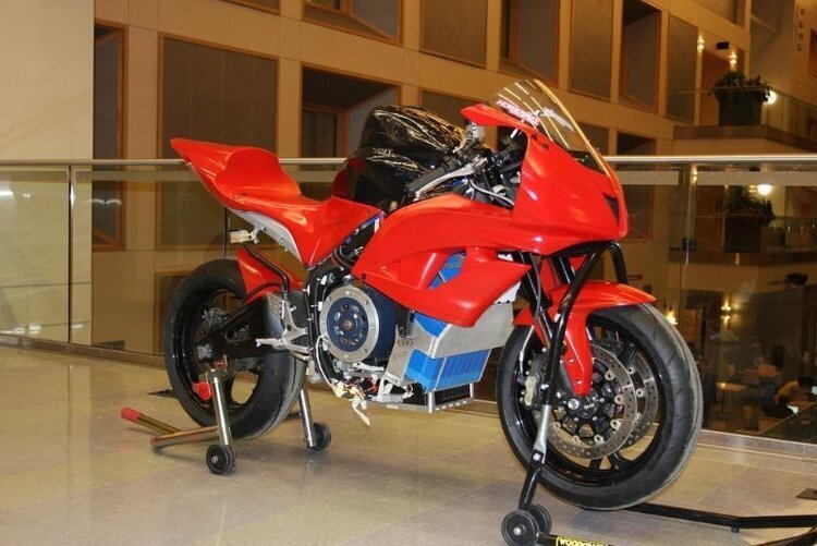
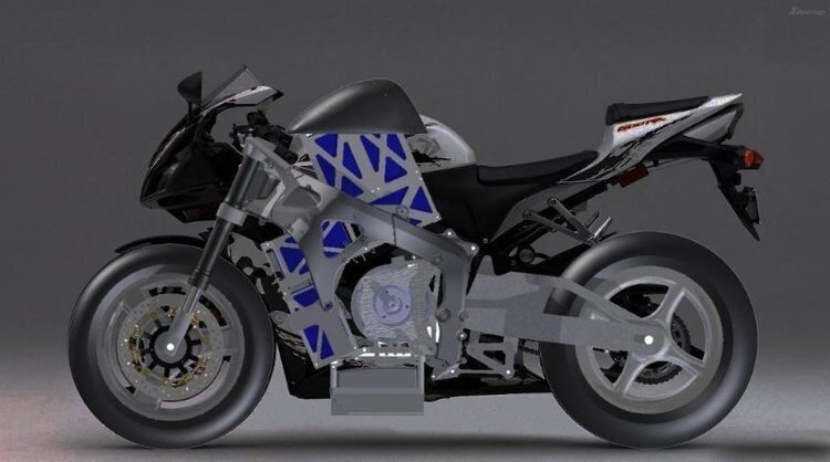
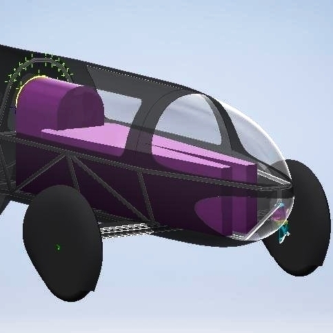
I was a part of Cornell Resistance Racing for 2 years. We were first an electric motorcycle team, and completed our project in 2016. In 2017, we became a Shell Eco Marathon team, competing in the prototype electric category of the Americas competition. I led the vehicle body subteam, responsible for aerodynamic design and optimization. Using primarily ANSYS Fluent CFD, I was able to construct physics simulations that helped us to iteratively improve the drag characteristics. I also built and designed an electric motor dynamometer that helped us pick the most suitable drivetrain components. In our inaugural year. we stunned the competition by achieving overall 5th place at the Americas competition, electric category with an efficiency of 167.4m/kWh.
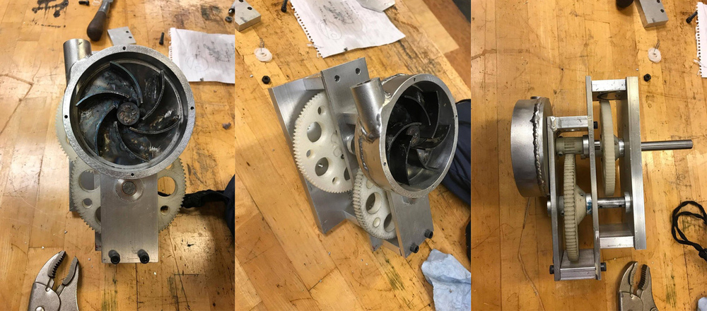
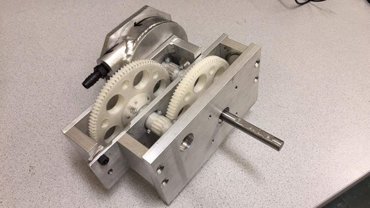
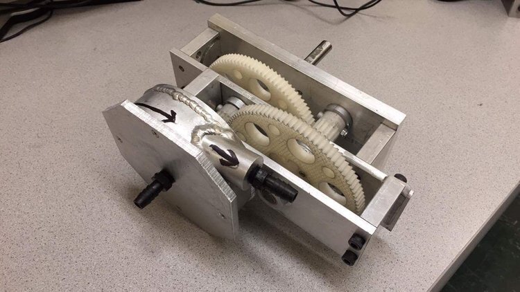
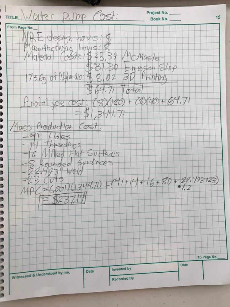
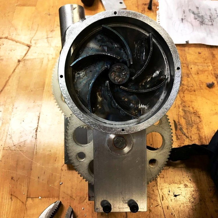
Completed as a part of MAE 2250 Mechanical Synthesis course design project. While most teams chose to design and fabricate a simple piston pump, our team chose to take on the challenge of creating the first centrifugal water pump in the course’s history (this course project has remained unchanged in the Cornell ME curriculum for a long time). We optimized the design of the impeller geometry according to a few research papers, and designed everything to be fabricated on basic manual mills and lathes with a budget constraint of $70. The frame and housing is all 6061 aluminum, while the impeller is low carbon steel. I did all of the welding on a Tungsten-Inert-Gas welder, and 3D printed the gears on my BigXY in Taulman 910 Nylon. Although the pump malfunctioned halfway into the trial due to a gear defect, it was able to satisfy the design challenge of pumping 1L of water before the unfortunate event.
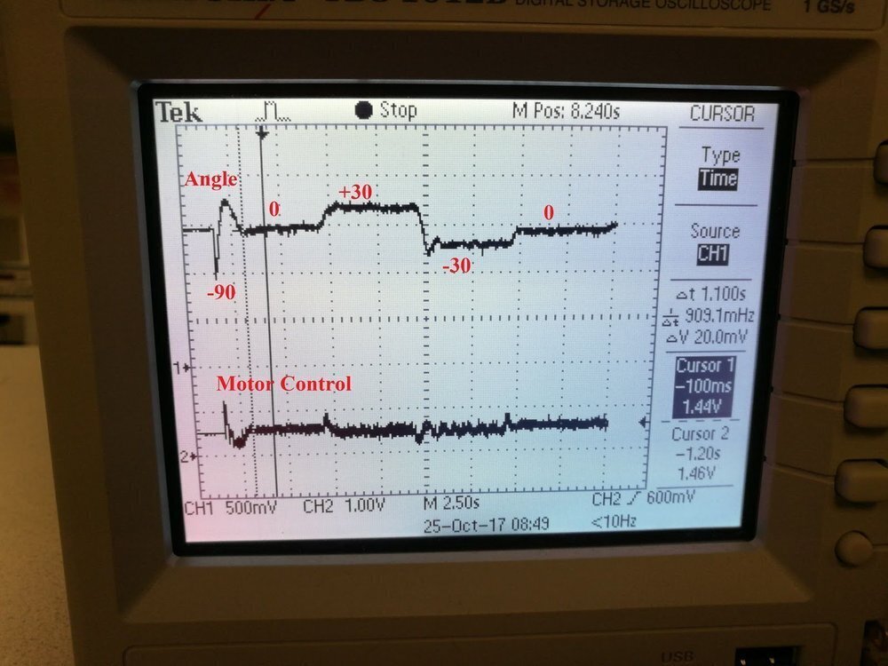
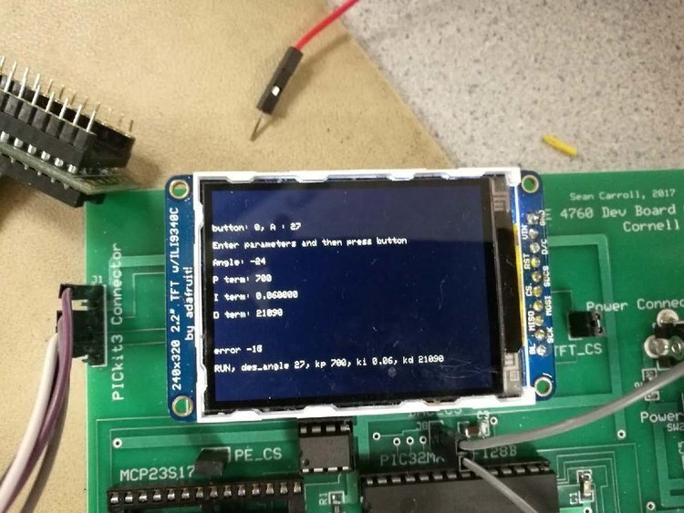
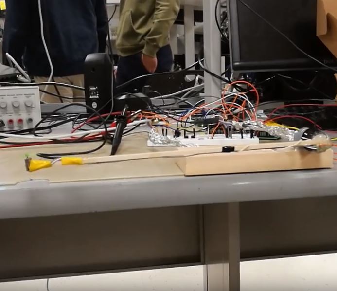
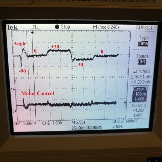
Goal was to control a pendulum with an attached drone motor driving a propeller, to various angular setpoints (-90 to 0, 0 to +30, +30 to -30, back to 0). Built control circuit from scratch using discrete components, as well as the mechanical setup. Derived physics model and developed discrete time PID controller to satisfy design requirements. All run in a multi-thread RTOS on PIC32.
This project was challenging because it required real time control of a nonlinear physical system, with a linear approximated model. Therefore, it required careful PID tuning to work on the very imperfect 1 DOF helicopter system. It was completed in two weeks with two other group members.
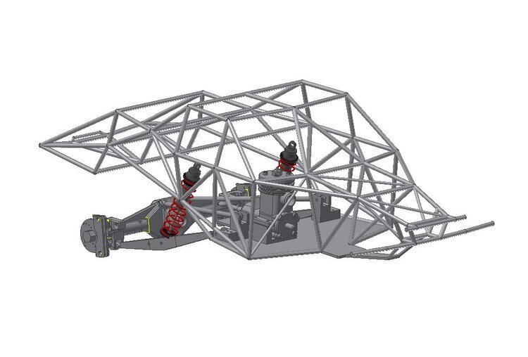
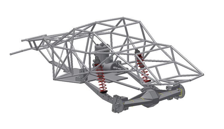
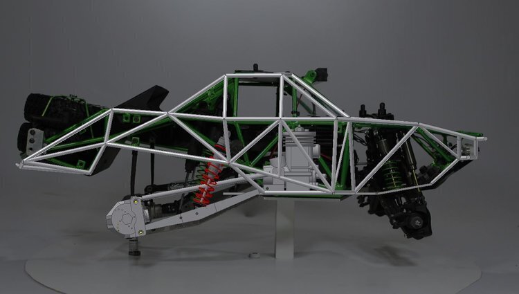
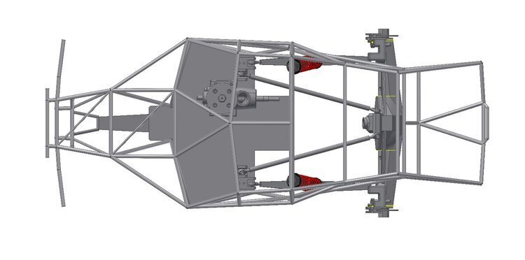
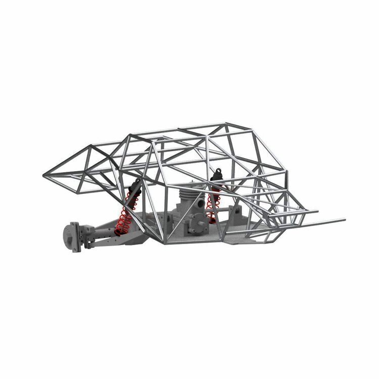
Inspired by BJ Baldwin’s Monster Energy Trophy Truck, I decided to attempt to create my own in RC car form. There have been a few successful examples done by enthusiasts in the RC community such as this. However, there are no solid axle trucks powered by a nitro engine. So I have set out to do just that, and created a custom roll cage matched to the original as much as possible, along with realistic wire actuated disc brakes. However, I just do not have the time and resources to devote to finishing a project like this right now. So this has been temporarily shelved until I get access to a welder again. Learned a ton about frame design tools along the way though.
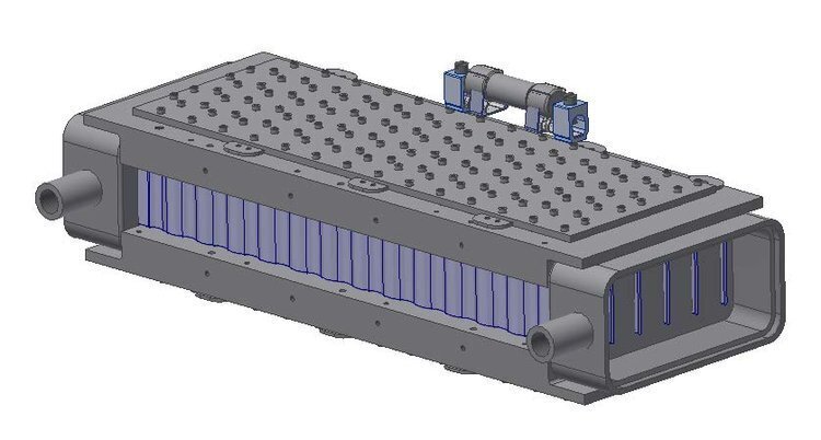
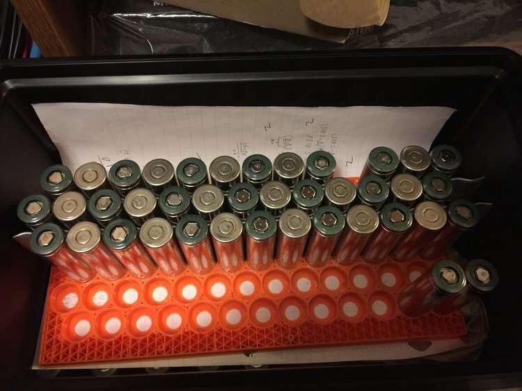
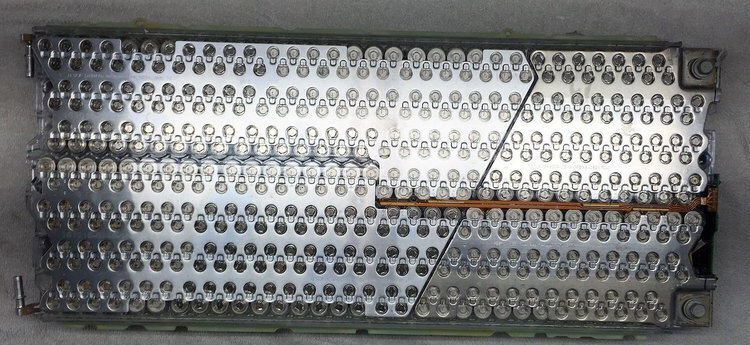
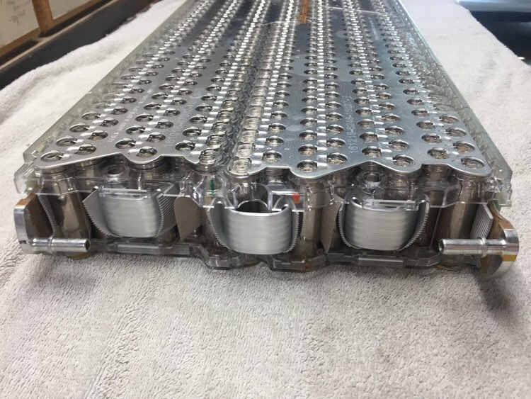
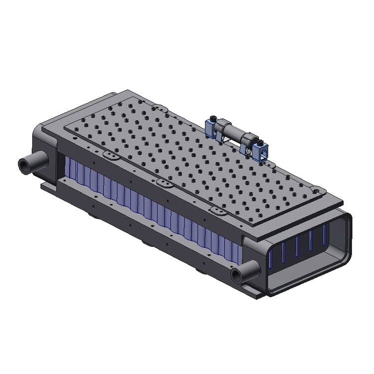
Probably one of my riskier projects, it began when I bought a Tesla battery module on Ebay from a salvaged 2017 Model S that only had 3700 miles on the odometer. I bought it for no other reason than the fact that it was even cheaper than the manufacturing cost per kWh of capacity, and I now have 444 NCA chemistry Lithium-Ion cells. Then I decided to make a watercooled electric bicycle battery pack from it, since I have never seen anyone do that before. And to say that I have Tesla cells in my E-bike battery just sounds so cool. This is a project still in progress, but I have finished most of the mechanical design, just need to find time to manufacture it. Also aiming to eventually replace the off-the-shelf BMS with a custom design of my own.
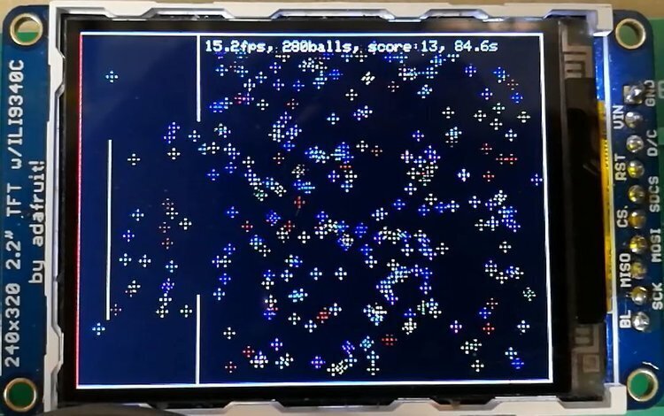
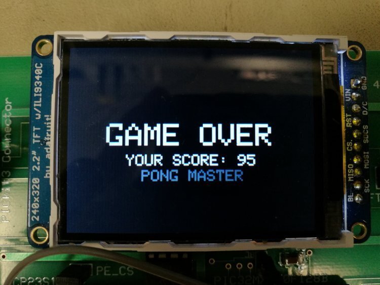
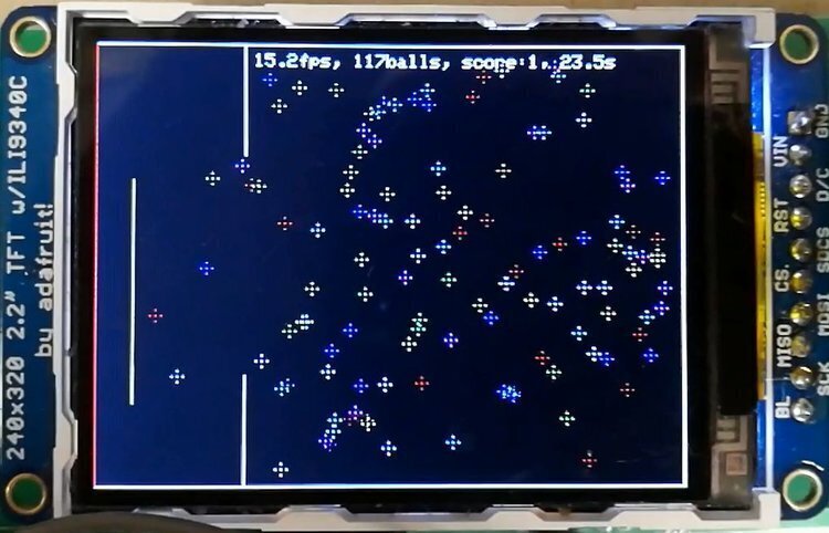
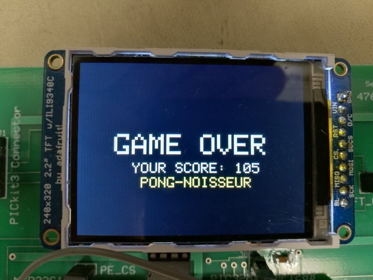
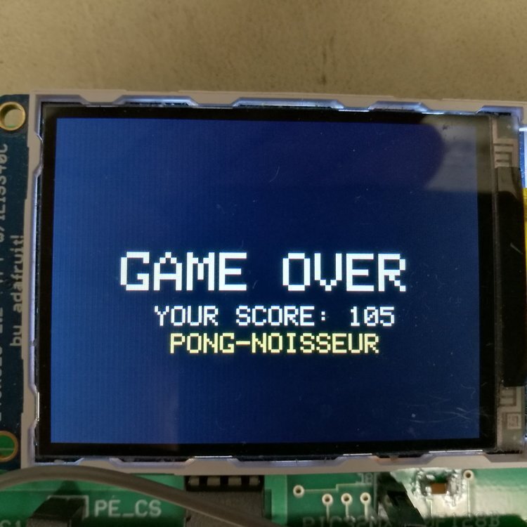
Goal was to run a pong game at 15 frames per second with as many balls as possible. MCU used was a 40Mhz PIC32, so it needed extensive optimization to handle real time physics calculations at a large scale. We simplified graphics and used direct memory access (DMA) for sound effects, achieving over 300 balls on screen simultaneously. Also coded in some funny end screen messages.
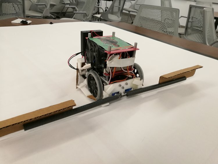
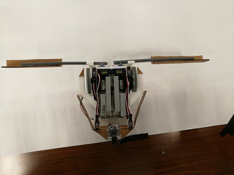

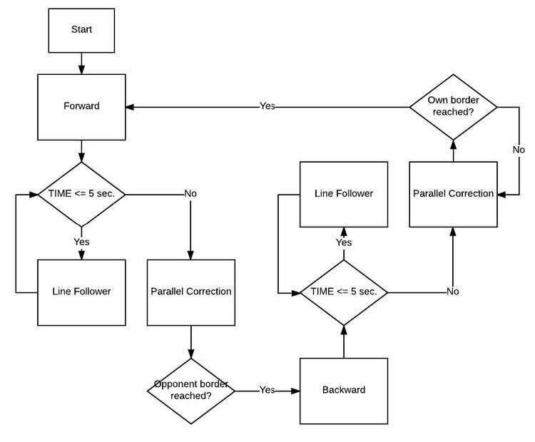
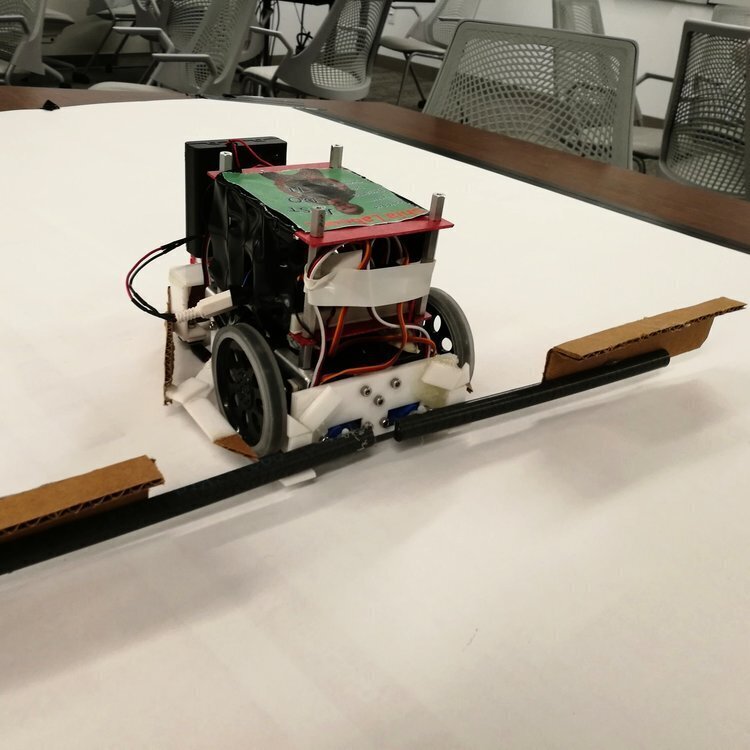
Completed as the final project of MAE 3780 Mechatronics course. Objective is to succeed in the game of Cube Craze, where two robots go head to head autonomously and try to push a field of 1” cubes to the opponent’s side. We came up with a robust design that yielded 5 wins and 2 losses. Utilizes Atmel 328P running a finite state machine, controlling servos and a custom built H-bridge. Feedback provided by color sensors all around.
This is where I got my start in engineering. The team was an extracurricular program at my high school. In my first year, I helped the team win the Nevada State Regional Competition undefeated, and became the lead mechanical engineer. We also made it to the FIRST World Championships, the first time in the team’s history. The next year I learned CAD and introduced the team to digital design as well as rapid prototyping, and later took on the role of team lead. We helped the robotics program grow from 6 people to over 30.
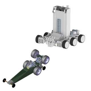
Completed as the ENGRI 1170 Introduction to Mechanical Engineering final design project. This is essentially a straight line vehicle designed to maximize its towing capacity as well as speed to excel in various events of the competition. We chose to create a two-deck vehicle that can be easily reconfigured to succeed in both the drag race and the tug-o-war events. The whole vehicle was designed in CAD, then fabricated out of fiberglass tubes for maximum stiffness. RC car tires were used to maximize grip. Overall, we were the first ranked team, placing second in both the pull force and tug-o-war competitions, and sixth in drag race. Most other teams did well in only one event. I worked with two others in this project.
This is somewhat of a silly project, but I wanted to figure out if the handle of a cast iron pan gets too hot to touch with only convection cooling while it is on a stove. Then I tested a supposedly improved handle design as advertised by the brand Solidteknics. Conclusion is both become unsafe to touch after just a few minutes of heating under medium heat, although the original design is much worse in transient behavior. The heating value of 200W is an approximation informed by the results of this article. Also compared results between Fluent CFD and Mechanical Heat Transfer, difference is that the mechanical module enables nonlinear convection coefficients while Fluent does not.
